Method and system of improving engine braking by variable valve actuation

a variable valve and actuation technology, applied in the direction of valve drives, non-mechanical valves, electrical control, etc., can solve the problems of ineffective realization of sophisticated control,/or magnitude difficulty in adjusting the timing of engine valve lift, etc., to improve engine performance, finely tuned amount of braking, and enhanced swirl or mixing

Inactive Publication Date: 2002-05-16
DIESEL ENGINE RETARDERS
View PDF0 Cites 18 Cited by
  • Summary
  • Abstract
  • Description
  • Claims
  • Application Information

AI Technical Summary

Benefits of technology

0058] In another embodiment of the present invention, the separation of the opening and closing times of each valve servicing a cylinder, and each valve's lift, may be varied by providing a separate means for actuating each valve. The ability to vary the timing and lift of each valve is an important improvement over conventional systems. For example, the ability to maintain certain engine valves closed during the combustion or braking cycle, allows the system of the present invention to convert a multi-valve engine into a conventional one intake or exhaust valve system. Any number of engine valve combinations may be used, i.e., multiple intake valves may be cycled with a single exhaust valve or vice versa.
0059] When used in conjunction with an engine in the firing (positive power) mode, an embodiment of the present invention offers numerous advantages. For example, the amount of swirl or air-fuel mixing during the intake stroke can be finely tuned by controlling the following parameters: numbe...

Problems solved by technology

However, unlike the system described in the Cummins patent, the system described in the Jakuba patent conveys the compression-release motion to only one of the two exhaust valves associated with each engine cylinder.
The use of fixed profile cams makes it difficult to adjust the timing and/or magnitude of the engine valve lift needed to optimize engine performance for various engine operating conditions, such as different engine speeds during engine braking.
Common rail systems may provide virtually limitless adjustment to valve timing because the source of high pressure hydraulic fluid is constantly available for valve actuation.
To date, however, such sophisticated control, particularly in the seating of engine valves has not been effectively realized.
Two problems in particular that tend to discourage the use of common rail actuation systems are the expense of the components required to exercise the level of control called for, and the susceptibility of the system to complete failure in the event of a loss in hydraulic pressure.
Until these problems are solved, it is likely that lost motion systems will con...

Method used


Image

  • Method and system of improving engine braking by variable valve actuation
  • Method and system of improving engine braking by variable valve actuation
  • Method and system of improving engine braking by variable valve actuation

Examples


second embodiment

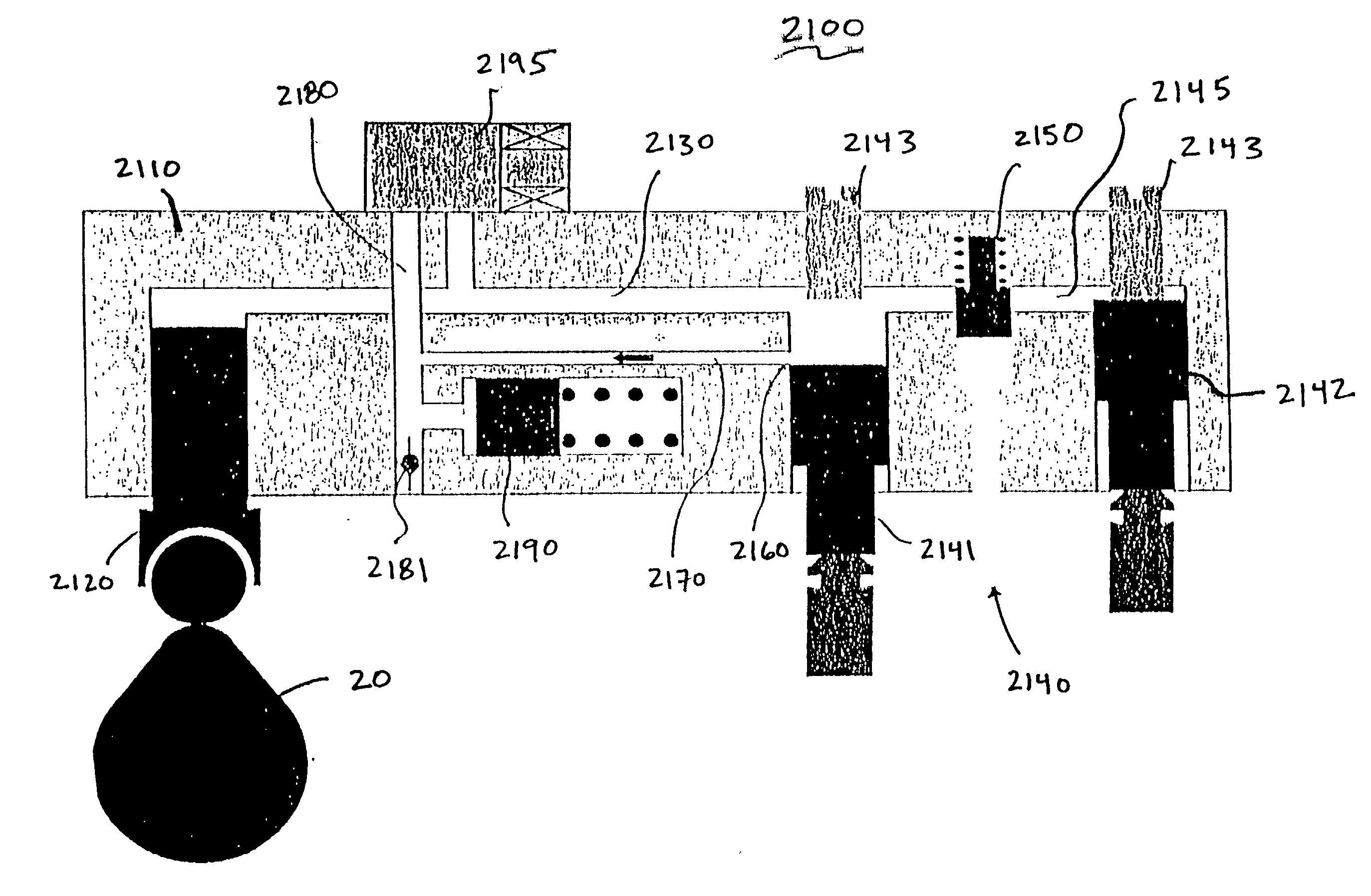
[0069] FIG. 6 is an example of the present invention, in which like elements to those in FIG. 5 are referred to with like reference numerals. The valve actuation system 2100 provides a fluid linkage 2130 between a master piston assembly 2120 and a slave piston assembly 2140. When isolated, the fluid linkage 2130 serves as a hydraulic link between the two piston assemblies so that motion of the master piston 2120 will transfer to the slave pistons 2141 and 2142. A trigger valve 2195 is provided to control the link between the master and slave pistons. A cams haft 20 is also provided. The cams haft includes various cam lobes capable of contacting the master piston.

[0070] Under normal operation, the trigger valve 2195 is open. The cams haft 20 turns in response to engine operation. The various cam lobes contact the master piston roller follower 2121 which in turn displaces the master piston. When the master piston assembly 2120 moves in response to a lobe of the cam 20, the oil volume ...

third embodiment

[0076] FIG. 7 is an example of the present invention, in which like elements to those in FIGS. 5 and 6 are referred to with like reference numerals. A high pressure pump (not shown) would supply sufficient pressure to open the engine valves (typically 4000 psi). The trigger valve 2195 would normally be in the closed position, and the engine valves (not shown) would be closed.

[0077] To open the engine valves, an electrical signal is sent to the trigger valve 2195. Upon receiving the appropriate signal, the trigger valve 2195 opens. High pressure fluid (typically engine oil) passes from fluid linkage 2180 through the trigger valve 2195 and into fluid linkage 2130. The high pressure fluid may be blocked from proceeding through bypass line 2147 to the second slave piston 2142 by inline check valve 2146. As pressure increases in the system, the force of the oil overcomes the force of the engine valve springs (not shown) and cylinder pressure, and moves the first slave piston 2141 downwar...


PUM


Abstract

The present invention relates to methods of improving engine braking of a reciprocating piston internal combustion engine by variable valve actuation. One embodiment of the present invention enables independent two-valve actuation for each cylinder, and engine braking horsepower can be optimized using two-valve braking at high engine speeds and one-valve braking at low speeds. Another embodiment of the present invention enables better a sequential valve actuation to reduce engine braking load and compliance. Another embodiment of the present invention enables better engine starting and warming up by controlling timing and lift of each valve.

Description

CROSS REFERENCE TO RELATED PATENT APPLICATION[0001] This application claims priority on U.S. Provisional Patent Application Serial No. 60 / 262,660, for Methods of Improving Engine Braking By Variable Valve Actuation, filed Jan. 22, 2001, a copy of which is incorporated herein by reference. This application is related to U.S. Provisional Patent Application Serial No. 60 / 066,097, for Sequential Intake and Exhaust Valve Opening System For Multi-Valve Internal Combustion Engines, a copy of which is also incorporated herein by reference.[0002] The present invention relates to a method and system for improving engine braking. In particular, the present invention relates to methods and systems using variable valve operation to improve engine braking performance.[0003] Valve actuation in an internal combustion engine is required in order for the engine to produce positive power. During positive power operation of an engine, one or more intake valves may be opened to allow air and fuel into a...

Claims


Application Information

Patent Timeline
IPC IPC(8): F01L9/11F01L13/06F02D13/04F02D45/00
CPCF01L1/08F01L9/021F01L2760/00F01L2001/34446F01L13/06F01L9/11
Inventor YANG, ZHOUEGAN, JAMES F. III
Owner DIESEL ENGINE RETARDERS
Why Eureka
Try Eureka