Quality control device for voice packet communications

a quality control and packet communication technology, applied in data switching networks, frequency-division multiplexes, instruments, etc., can solve problems such as packet loss, packet loss, delay, and jitter

Inactive Publication Date: 2002-05-30
OKI ELECTRIC IND CO LTD
View PDF14 Cites 45 Cited by
  • Summary
  • Abstract
  • Description
  • Claims
  • Application Information

AI Technical Summary

Benefits of technology

[0037] In the irreversible compression method, there is the possibility that data loss (for example, loss at the bit level) will occur. By this compression, data storage is reduced to, for example, about one several tenth to one several hundredth (in the lossless compression method, it is reduced to, for example, about one second to one ninth). The voice data is to be finally perceived by the auditory organs of a person, such as a user of the packet communications device 12. Therefore, even if the data is not strictly reconstructed into the original state in which it is not compressed, and even if a part of the data is lost, there is no problem if it is in an allowable limit. Therefore, for example, from viewpoint of the improvement in the real-time responsiveness of communication, it is advantageous to reduce the data size by high compressibility and carry out irreversible compression that is convenient for improving substantial transmission efficiency rather than to seek accuracy of the data obtained by decompression.
[0065] In order to reduce the possibility of occurrence of the aforementioned exhaustion in the thus constructed buffer device 16, the longer the queue is, the better. However, if the queue is too long, the transmission delay becomes substantially long, and this will increase the possibility that, for example, the response, which is brought by the voice packet PI from the voice communications device 11, to the contents of voices in a bidirectional conversation might be unnaturally delayed. For this reason, the buffer device 16 controls the buffer memory 32 so as to always maintain a fixed amount of packets (i.e., a queue with a fixed length) in cooperation with both the complementary-packet inserting device 19 and the packet deleting device 20.
[0069] Generally, a device that decodes a voice by a packet unit is needed to decode packets at a fixed time interval that corresponds to the decoding unit time. However, the application of this embodiment makes it possible to precedently process the voice presence / absence judgment of the packets and the deletion of the packets. In other words, they can be processed when the load of a processor is low, and the operating ratio of the processor can be improved.
[0070] Additionally, when voice packets PI to be deleted are determined, the packet deleting device 20 functions so that the to-be-deleted voice packets PI can disperse without succession on a queue as completely as possible, and a necessary number (deletion number) of voice packets can be deleted while deleting the voice packets judged as voice-absence as fully as possible.
[0073] As a result of this deletion, a packet less similar to a voice-presence packet, described later, (i.e., a packet like a voice-absence packet) might remain at a position on the queue, and a packet higher in likeness degree to voice presence than the remaining packet lower in likeness degree to voice presence might be deleted from a position on the queue. However, when seen as the entire queue, it is very likely that the quality of voice output obtained when decoded will improve even greater than in a case where the deletion of packets consecutive on a queue is allowed.
[0099] However, there is a case where the queue length that has once fallen below the higher threshold TH by the deletion frequently exceeds the higher threshold TH again because of a reduction in the deletion number, and an excessive load is imposed on the processing of the packet deleting device 20 or the voice presence / absence judging device 21 in relation to the reading of the scanning signal SC. There is a solution in this case to increase the deletion number and reduce the load.

Problems solved by technology

However, the Internet was originally developed for data communications that do not require real time transmission, and the packet transmission on the Internet is not guaranteed qualitatively.
Therefore, there is the possibility that phenomena, such as packet-lacking (packet loss), delay, and jitter, that deteriorate a decoded voice will occur on the Internet.
Therefore, in a case where this buffer device is used, if the arrival of a voice packet at a receiver is delayed for more than the fixed time because of, for example, the influence of jitter, the voice packet is not stored onto the buffer device, and only the reading continues, and, as a result, voice packets to be read out will be exhausted.
Therefore, disadvantageously, the number of packets in the buffer device gradually increases, and a transmission delay is lengthened with the lapse of time.
If the transmission delay becomes long, the response to the contents of speech, for example, in a bidirectional conversational voice will be unnaturally delayed, and the quality of communication will fall.
If deleted, effective voice data needed when decoded will be lost, and, if inserted, unnecessary voice data will be mixed when decoded.
Therefore, these are operations that deteriorate the quality of decoded voice output, and, if the deletion or insertion is successively carried out from or onto the series of voice packets, the possibility that the degree of deterioration will become significant is high.

Method used


Image

  • Quality control device for voice packet communications
  • Quality control device for voice packet communications
  • Quality control device for voice packet communications

Examples


second embodiment

[0112] (B) Second Embodiment

[0113] Only the difference between the first embodiment and the second embodiment will be described hereinafter.

[0114] (B-1) Structure and Operation of the Second Embodiment

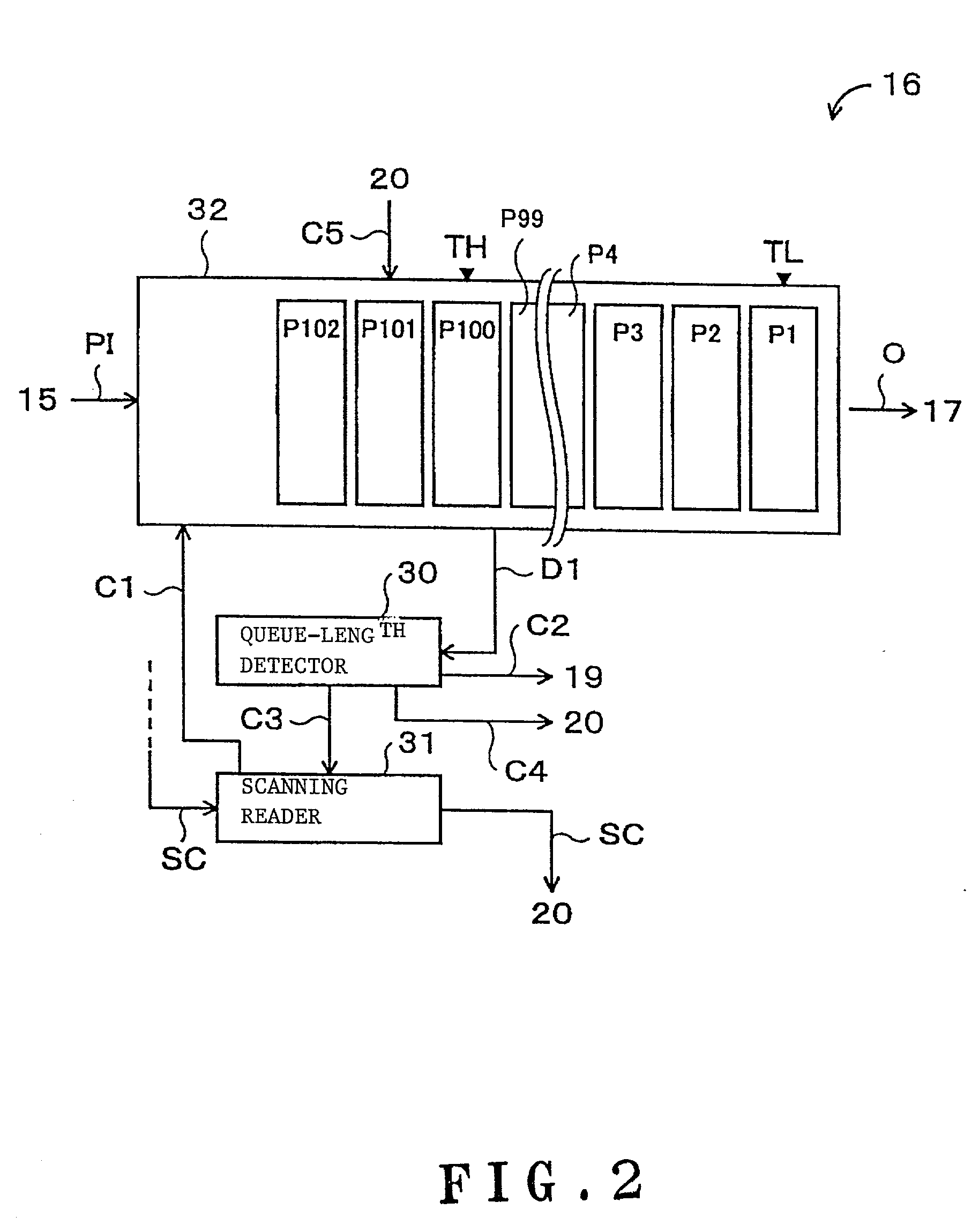
[0115] FIG. 3 shows an internal structure of a fluctuation absorbing buffer device 46 provided instead of the fluctuation absorbing buffer device 16 of FIG. 2 in this embodiment.

[0116] The buffer device 46 is an element that corresponds to the buffer device 16 of the first embodiment, and the basic function thereof is the same as that of the buffer device 16.

[0117] The whole structure of a voice communications system 40 that includes a voice communications device 42 on the receiving side where the buffer device 46 is mounted is as shown in FIG. 8.

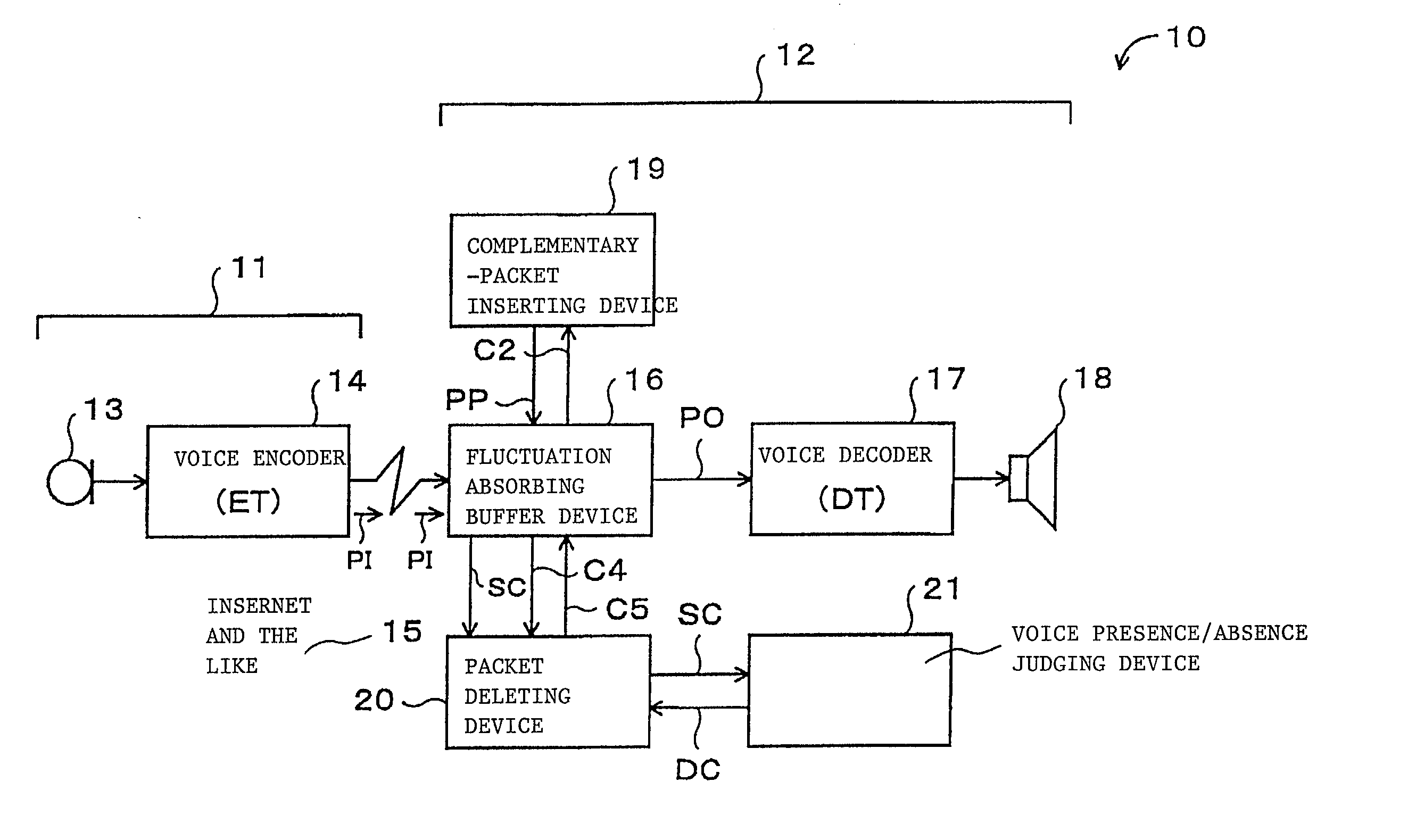
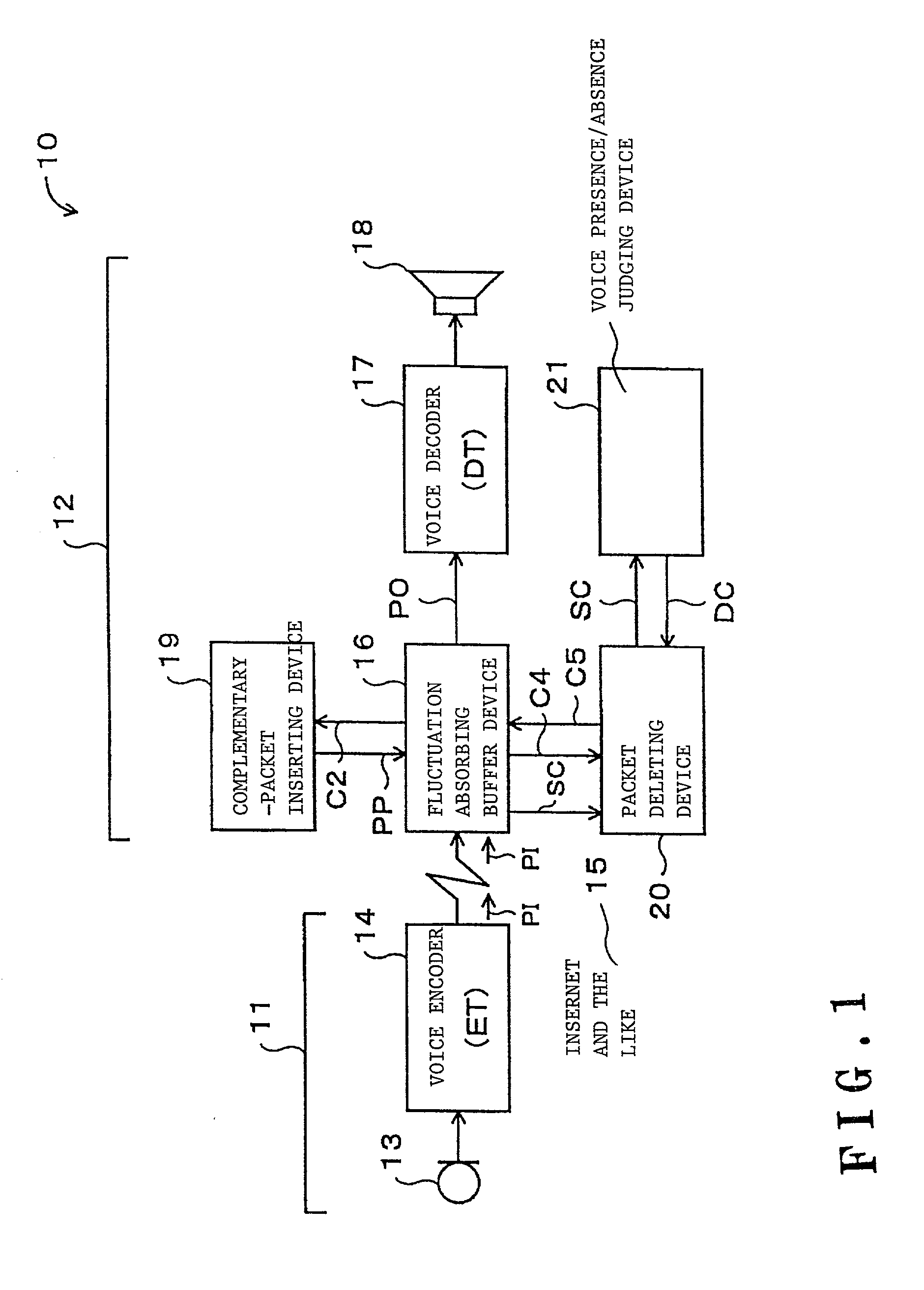
[0118] In other words, the structure of the voice communications system 40 of this embodiment is basically the same as that of the voice communications system 10 of the first embodiment shown in FIG. 1.

[0119] In FIG. 8, the voice communication...

third embodiment

[0146] (C) Third Embodiment

[0147] Only the difference between this embodiment and the first embodiment will be described hereinafter.

[0148] This difference is limited to the fact that the higher threshold (TH) fixed in the first embodiment can be dynamically changed.

[0149] (C-1) Structure and Operation of the Third Embodiment

[0150] A structure of a principal part of a voice communications system 60 of this embodiment is shown in FIG. 9.

[0151] In FIG. 9, the functions of each component and each signal, to which the same reference character as that of FIG. 1 is given, are the same as those of FIG. 1.

[0152] Therefore, in FIG. 9, the structure of the voice communications device 62 of this embodiment is different from that of the voice communications device 12 in that the device 62 has a microphone 63, a voice encoder 67, and a dual-talk detector 64, in the internal structure of a fluctuation absorbing buffer device 66.

[0153] Further, the voice communications device 61 of this embodiment...

fourth embodiment

[0173] (D) Fourth Embodiment

[0174] Only the difference between this embodiment and the first and third embodiments will be described hereinafter.

[0175] (D-1) Structure and Operation of the Fourth Embodiment

[0176] A structure of a principal part of the voice communications system 70 of this embodiment is shown in FIG. 11.

[0177] In FIG. 11, the functions of each component and each signal, to which the same reference characters as that of FIG. 9 are given, are the same as those of FIG. 9.

[0178] That is, the voice communications system 70 of this embodiment has a structure in which the dual-talk detector 64 in the voice communications device 62 of the voice communications system 60 of the third embodiment is substituted with a power-variation-difference computing unit 71 and a zero-crossing counter 72.

[0179] With this structure, in the third embodiment, the control signal C11 is changed in accordance with the analytic result of a conversation pattern that corresponds to the tendency of ...


PUM


Abstract

A quality control device which improves the quality of voice packet communication. The quality control device used for voice packet communications for transmitting voice packets through a quality non-assurance type network includes a buffer memory for temporarily storing voice packets received through the network and forming a queue of the received voice packets, a queue operating device for operating the queue in accordance with an operation control signal to be supplied, a sequence examining device for examining vocal properties of a sequence of voice information contained in a plurality of voice packets that constitute the queue stored in the buffer memory, and an operation control device for changing the operation control signal in accordance with an examination result of the sequence examining means.

Description

[0001] 1. Field of the Invention[0002] The present invention relates to a quality control device for voice packet communications that uses a packet network of, for example, the Internet.[0003] 2. Description of Related Art[0004] Recently, techniques are been proposed for transmitting a voice signal in real time through a packet network of, for example, the Internet, and devices therefor are being introduced for actual use.[0005] However, the Internet was originally developed for data communications that do not require real time transmission, and the packet transmission on the Internet is not guaranteed qualitatively. Therefore, there is the possibility that phenomena, such as packet-lacking (packet loss), delay, and jitter, that deteriorate a decoded voice will occur on the Internet.[0006] Therefore, if the Internet is used for a communications function, such as telephone communications, that require real-time responsiveness, a buffer device is needed to prevent transmission intermi...

Claims


Application Information

Patent Timeline
Patent Type & Authority Applications(United States)
IPC IPC(8): G10L19/00G10L21/02H04L12/64
CPCG10L25/69H04L12/6418G10L21/0364H04L2012/6489H04L2012/6481
Inventor YOKOYAMA, ATSUSHIAOYAGI, HIROMIYAMAGUCHI, NOBUYUKIAKIE, KAZUYOSHI
Owner OKI ELECTRIC IND CO LTD
Why Eureka
Try Eureka