High-speed tool steel gear cutting tool and manufacturing method therefor

a cutting tool and high-speed tool technology, applied in the direction of gear-teeth manufacturing apparatus, natural mineral layered products, record information storage, etc., can solve the problems of affecting the life the existence of around 1 to 5% residual austenite cannot be avoided, and the chip is susceptible to adhesion to the surface of the cutting edge of the gear cutting tool

Inactive Publication Date: 2002-06-27
MITSUBISHI MATERIALS CORP
View PDF0 Cites 30 Cited by
  • Summary
  • Abstract
  • Description
  • Claims
  • Application Information

AI Technical Summary

Problems solved by technology

However when used in high-speed gear cutting, this is susceptible chipping, particularly at the ridge line intersection of the rake face and the relief face of the cutting edge, so that the useful life is reached in a comparatively short time.
However when used in high-speed gear cutting of gears such as low-alloy steel or mild steel with extremely high viscosity, since the affinity between the chips produced by the cutting and the (Ti, Al)N layer or the (Ti, Al)CN layer constituting the hard coating layer is high, the chips are susceptible to adhering to the surface of the cutting edge of the gear cutting tool.
Consequently, even if the residual austenite diffusingly distributed in the matrix of the martensite structure formed by the quenching is transformed into martensite, the existence of around 1 to 5% residual austenite cannot be avoided.
In particular, regarding the cooling temperature, if the cooling temperature is higher than -150.degree. C., it is difficult to transform the residual austenite into the desirable martensite...

Method used


Image

  • High-speed tool steel gear cutting tool and manufacturing method therefor
  • High-speed tool steel gear cutting tool and manufacturing method therefor
  • High-speed tool steel gear cutting tool and manufacturing method therefor

Examples


first embodiment

[0042] First Embodiment

[0043] A cutting tool of the present invention will now be specifically described by means of an embodiment.

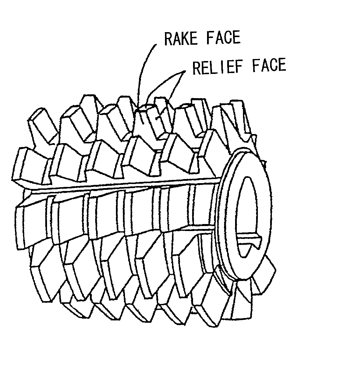
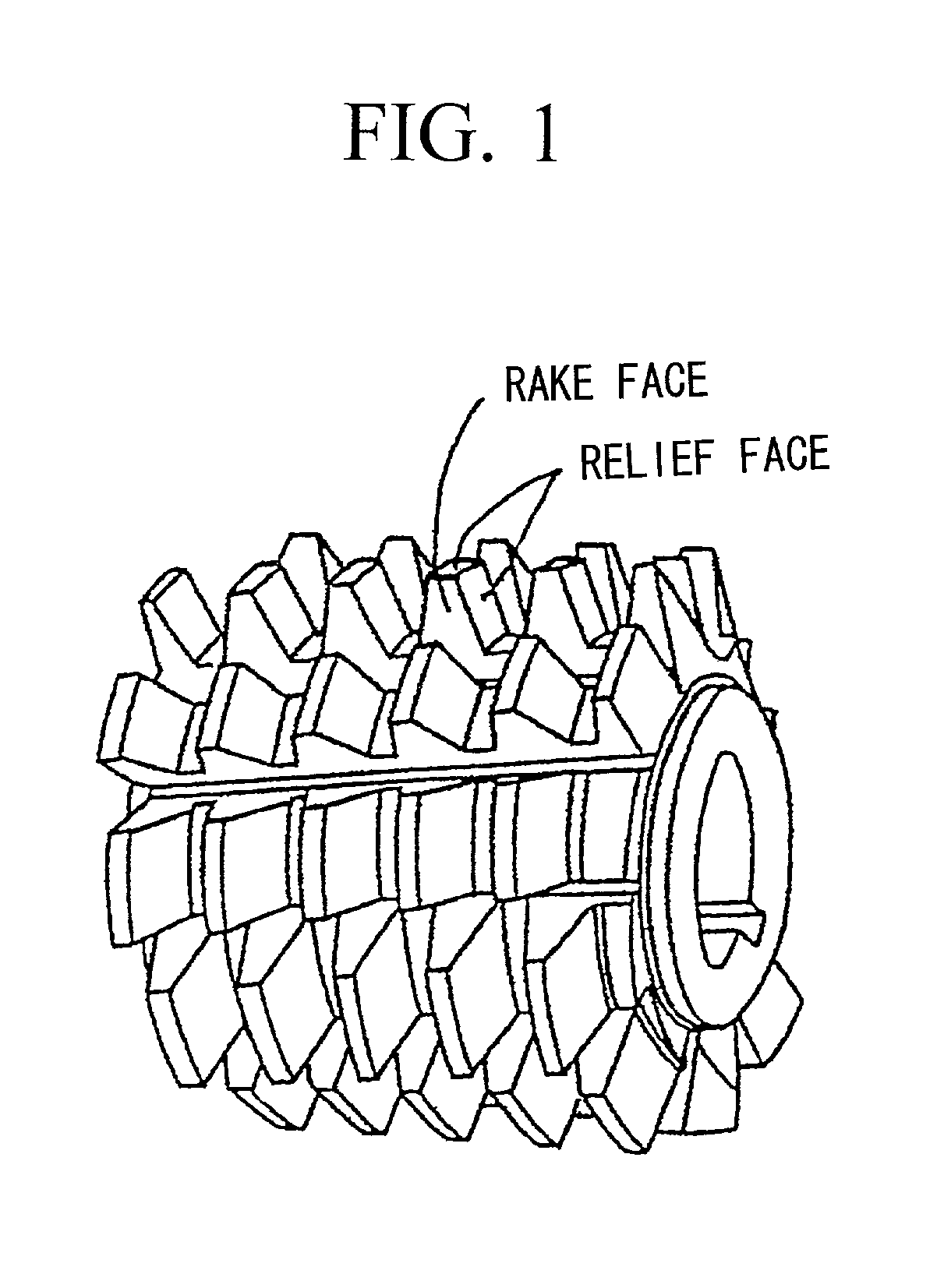
[0044] Three types of high-speed tool steel ingots prescribed by Japan Industrial Standard JIS SKH55, SKH56 and SKH57, all having an outside diameter of 300 mm were prepared, and each of the ingots was subjected to hot forging in a condition heated to a temperature of 1130.degree. C., to produce bar stock of 150 mm diameter. These bar stocks were then held for 30 minutes at 880.degree. C. and fully annealed after which they were each cut to a length of 100 mm, and then milled so that all were rough processed into tool materials of a shape corresponding to a final shape shown in FIG. 1. These tool materials were then heated to 1250.degree. C. in a nitrogen atmosphere and held for 20 minutes, and then cooled while maintaining the cooling speed at 40-120.degree. C. / minute by adjusting the blast proportion of pressurized nitrogen gas to effect quenching, the...

second embodiment

[0053] Second Embodiment

[0054] Next is a specific description by means of an embodiment, of a coated gear cutting tool of the present invention.

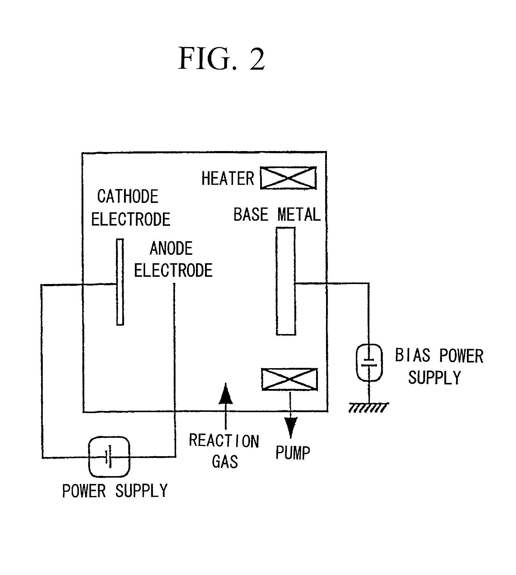
[0055] As a base metal made of a high-speed tool steel, a single thread hob for a gear made from a JIS SKH 55 material and having an outside diameter of 60 mm, and an overall dimension of 60 mm (module: 2) prescribed in JIS B 4354, and a pinion cutter made from the same material JIS SKH 55 and with 50 teeth and a pitch circle diameter of 100 mm (module: 2) prescribed by JIS B 4356 were prepared. These base metals were then ultrasonic cleaned in acetone and respectively placed in a dry condition in a conventional cathodic arc ion plating apparatus as shown for example in FIG. 2. On the other hand, for the cathode electrode (vapor source), metal alloys of respective predetermined component compositions were selected for predetermined combinations, from the first thin layer forming Ti--Al alloy and the second thin layer forming Ti--Al--Ta alloy...


PUM

PropertyMeasurementUnit
Angleaaaaaaaaaa
Temperatureaaaaaaaaaa

Abstract

The invention provides a high-speed tool steel gear cutting tool in which fracture or chipping does not occur at the cutting edge, and which realizes excellent cutting performance over long periods. Moreover, a method of manufacturing a gear cutting tool including: a step for quenching a tool material comprising high-speed tool steel and which has been rough processed to a shape corresponding to a final shape of a gear cutting tool, to transform a structure of the tool material into martensite, a step for temperling the tool material after quenching to transform any residual austenite dispersingly distributed throughout a matrix of the martensite structure formed by the quenching, into martensite, and a step for finishing the tool material after tempering to a final shape, is characterized in that the tool material after quenching is subjected to sub-zero treatment involving cooling and holding at a temperature of less than -150° C.

Description

[0001] 1. Field of the Invention[0002] The present invention relates to a high-speed tool steel gear cutting tool (hereunder referred to simply as a gear cutting tool) in which fractures or chipping (minute fractures) do not occur at the cutting edge even when performing gear cutting at high-speed, and which realizes excellent cutting performance over long periods, and a manufacturing method therefor.[0003] 2. Description of the Related Art[0004] Heretofore, in the gear cutting of tooth profiles for various gears used as constituent members for automobiles, aircraft, and various drive units, a gear cutting tool such as for example the hob (solid hob) shown in FIG. 1, a pinion cutter, or a shaving cutter are used.[0005] Furthermore, manufacture of this gear cutting tool by the following steps as illustrated hereunder in (a) to (e) it also well known.[0006] (a) Hot forge an ingot of high-speed tool steel at a temperature of 1100 to 1150.degree. C. to make a bar with an outer diameter ...

Claims


Application Information

Patent Timeline
IPC IPC(8): C21D6/04C21D9/22C23C14/02C23C14/06
CPCB23F21/16C21D6/04C21D9/22C21D2211/008C23C14/02C23C14/0641Y10T407/17C23C28/04C23C30/00Y10T407/27Y10T428/24975Y10T428/265C23C14/0664
Inventor YAMADA, YASUYUKIICHIMIYA, NATSUKIMAEDA, KOICHITANAKA, YUSUKETANAKA, KAZUAKI
Owner MITSUBISHI MATERIALS CORP
Why Eureka
Try Eureka