
Aluminum alloy product refinement and applications of aluminum alloy product refinement

a technology of aluminum alloy and product refinement, which is applied in the field application of aluminum alloy product refinement, can solve the problems of inability to use as a dispersoids for recrystallation control, dispersion strengthening, and inability to form clusters in metal in situ,

Inactive Publication Date: 2002-07-04
ARCONIC INC
View PDF5 Cites 8 Cited by
  • Summary
  • Abstract
  • Description
  • Claims
  • Application Information

AI Technical Summary

Benefits of technology

[0032] Accordingly, it is an object of the present invention to provide a method for increasing the number densities of dispersoids in the liquid state and which then remain stable and dispersed in the solid state in metal alloys.
[0034] It is a further object of the present invention to produce uniformity in the dispersion of finely sized ceramic phase particles in metal and in alloys.
[0036] It is another object of the present invention to produce uniformly distributed, finely sized ceramic phase particles dispersed in-situ in a metal alloy in a process providing reaction times shorter than conventional approaches.

Problems solved by technology

Although conventional ceramic phase formation processes in metal offer some possibilities for the production of a wide range of reinforcement particle types and improved compatibility between the reinforcement and the matrix, the in-situ formed ceramic particles in metal are too large, e.g., on the order of several microns, and tend to form clusters.
In-situ formed ceramic particles having these sizes, i.e., of several microns, are candidates for use as reinforcement in a composite, but are not suitable for use as dispersoids for recrystallation control, for dispersion strengthening, or for use as a component for structure refinement.

Method used


Image

  • Aluminum alloy product refinement and applications of aluminum alloy product refinement

Examples


example

[0066] A first component melt of 1.5 Kg of aluminum-2% titanium (1016 grams Al, 484 grams Ti) provided by the Aluminum Company of America, Alcoa Technical Center, Alcoa Center, PA was prepared and heated to about 983.degree. C. A second component mixture (922 grams total) of carbon particles and a salt (700 grams) containing about 48% NaCl, 48% KCl, 2.2% MgCl.sub.2, and 1.8% CaCl.sub.2 by weight was prepared and heated to about 200.degree. F. overnight. The preheated first and second components were added together in a crucible and heated to a temperature of about 983.degree. C.

[0067] A mechanical stirring was applied by graphite propeller inserted into the crucible. A lid was placed to cover the crucible during reaction and to permit insertion of the graphite propeller and a thermocouple. After vigorous stirring and reaction for 15 minutes, the salt was skimmed, and the melt was cast into 1.5 inch diameter graphite molds. After cooling, the casting was cut for characterization.

[006...


PUM

PropertyMeasurementUnit
Lengthaaaaaaaaaa
Lengthaaaaaaaaaa
Fractionaaaaaaaaaa

Abstract

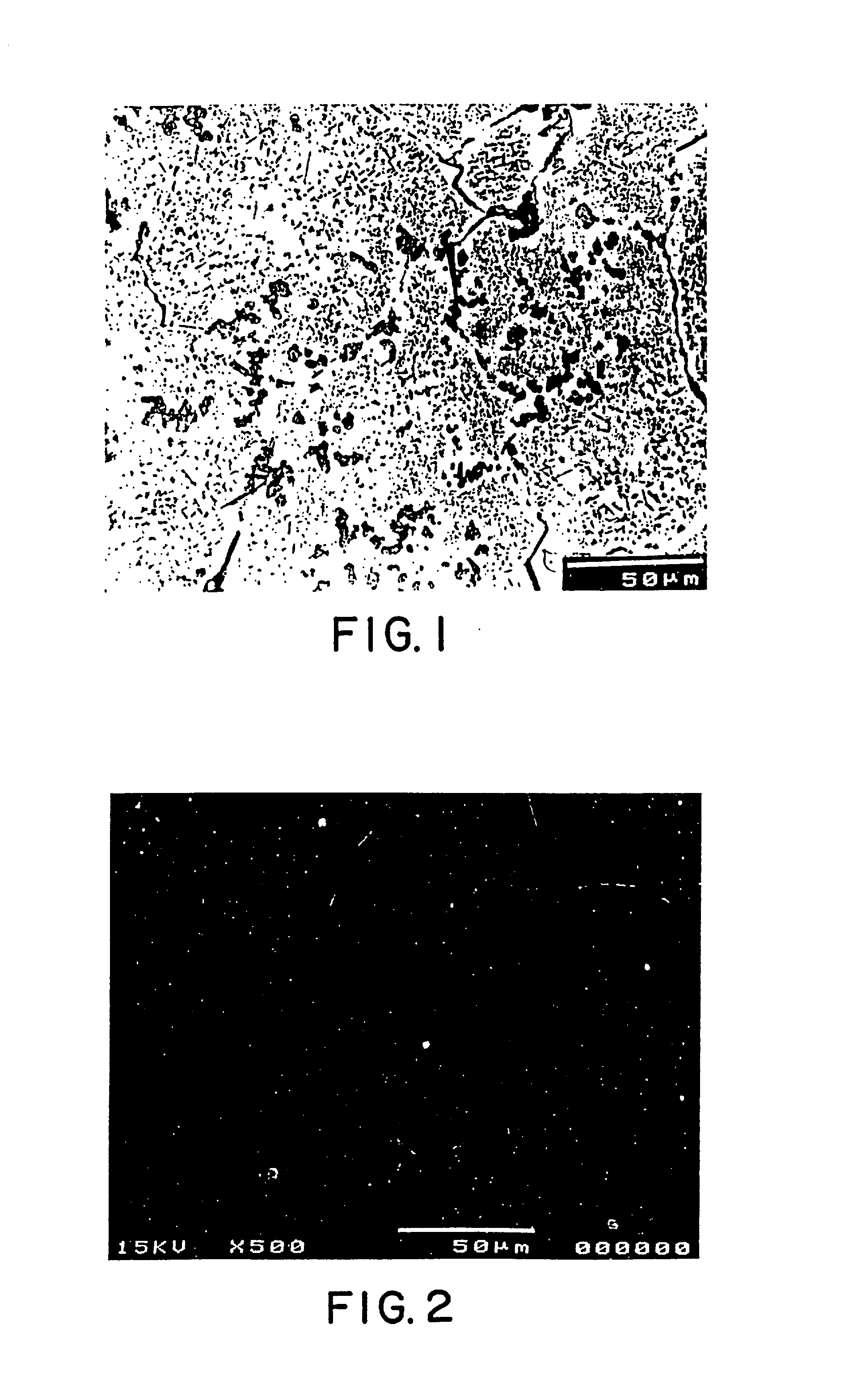
A novel product composed of a ceramic phase particle dispersoid in metal, including uniformly distributed, finely sized carbide phase particles formed in situ in a molten metal and a novel method for producing such a ceramic phase particle dispersoid in metal are disclosed. A salt-based liquid state reaction involving a liquid metal / alloy containing a liquid Ti, B, Si, Sc, Hf, Nb, Ta, Zr, Mo, Al (when the molten metal matrix is not aluminum), or V and a halide salt containing carbon particles forms a uniform distribution of finely sized ceramic phase particles formed and dispersed in-situ in the metal matrix. The ceramic dispersoid in metal product of the present invention includes at least about 50 volume percent of a matrix metal of aluminum; and up to about 50 volume percent of a uniform distribution of finely sized ceramic phase particles formed and dispersed in-situ in the aluminum metal matrix, wherein the finely sized ceramic phase particles have an average particle diameter of less than about 2.5 microns, and wherein the uniform distribution consists of a substantially cluster-free distribution of no more than two particles attached to one another at a magnification of 500x.

Description

[0001] This patent application is a continuation-in-part of prior, U.S. patent application Ser. No. 09 / 053,033, filed Apr. 1, 1998, now U.S. Pat. No. 6,036,792.[0002] 1. Technical Field[0003] The present invention relates to a composition containing uniformly dispersed, finely sized, liquid-state-in-situ-formed ceramic particles in metal and metal alloys, and to products containing the uniformly dispersed, finely sized ceramic particles formed in metal and metal alloys by the liquid-state in-situ process of the present invention. In one aspect, the present invention relates to a composition containing uniformly dispersed, finely sized, liquid-state-in-situ-formed titanium carbide particles in aluminum and aluminum alloys, and to products containing the uniformly dispersed, finely sized titanium carbide particles formed in aluminum and aluminum alloys by the liquid-state in-situ process of the present invention.[0004] 2. Background[0005] The aluminum and aerospace industries have lon...

Claims


Application Information

Patent Timeline
IPC IPC(8): C22C1/10C22C32/00
CPCC22C1/1036C22C32/0052
Inventor CHU, MEN GLENNRAY, SIBA P.
Owner ARCONIC INC
Learn More