Process for generating hydrogen and apparatus for generating hydrogen

a hydrogen and hydrogen technology, applied in the direction of process and machine control, liquid-gas reaction process, chemical/physical/physico-chemical stationary reactor, etc., can solve the problems of large energy loss, slow co-shift reaction, and decrease in reaction ra

Inactive Publication Date: 2002-07-04
TOYOTA CENT RES & DEV LAB INC
View PDF2 Cites 38 Cited by
  • Summary
  • Abstract
  • Description
  • Claims
  • Application Information

AI Technical Summary

Problems solved by technology

However, when the reaction temperature is too low, the reaction rate decreases.
Moreover, the increment of the steam concentration results in a large energy loss, because it is necessary to supply a thermal energy required for vaporizing the water.
Moreover, the CO shift reaction is usually slow.
In addition, the lower the reaction temperature is, the slower the CO shift reaction is.
In the removal of CO, however, no such means is available.
In particular, in an electrode of fuel cells, CO causes poisoning.
For instance, when a reformed fuel gas, which contains CO, contacts with the electrode of fuel cells, the battery performance is degraded by the CO poisoning.
When the temperature control, etc., are taken into consideration altogether, such means, however, are complicated and large-sized, and are accordingly expensive.
Therefore, such means do not conform to a small-sized purpose like a fuel cell, which utilizes a public utility gas, for cogeneration.
When the oxygen amount is less than the adequate amount, the harmful CO is supplied to an electrode of a fuel cell together with the reformed fuel so that the battery performance is degraded by the CO poisoning in the electrode.
At present, however, since no sensor, which can precisely detect the CO concentration in the reformed fuel gas, has been developed yet, the amount of oxygen to be supplied is determined based on the CO concentration, which has been measured in advance, so far.
By such a method, however, it is not possible to detect the variations of the CO concentration in the reformed fuel gas in proportion to the degraded states of the reforming catalyst, and accordingly it is difficult to vary the oxygen amount so as to respond to the variation of the CO concentration.
In the method, since the oxygen amount is adjusted excessively to oxidize CO so that the CO poisoning in the electrode of the fuel cell is suppressed more preferentially, it is inevitable to uselessly consume H.sub.2 by the excessive oxygen.
Accordingly, the multi-stage hydrogen generation process does not comply with the purpose of downsizing a fuel cell for boarding on automobiles, for instance, or the purpose of responding to the variation of the demanded hydrogen amount.
In the meantime, it is difficult to generate hydrogen.
Therefore, the conventional hydrogen generation process is not appropriate for an automotive fuel cell, for example.
In addition, when the conventional reforming catalysts are used at a high temperature falling in the range of from 700 to 900.degree. C., since the reactions of the conventional hydrogen generation process proceed in such a temperature region so fast enough that they reach the chemical equilibrium, it is impossible for the conventional reforming catalysts to reduce CO as illustrated in FIG. 7, for instance.
Therefore, it is considered difficult to carry out the steam reforming reaction and the CO shift reaction in a single reactor under the identical temperature environment.
However, the carbon dioxide adsorbent cannot infinitely adsorb the carbon dioxide.
Accordingly, when the adsorption saturates, it is difficult for the carbon dioxide adsorbent to thereafter adsorb carbon dioxide.
Accordingly, the entire hydrogen generation apparatus has become large-scale and expensive.
However, since it is difficult to absorb the carbon dioxide during the heating, CO co-generates at the reactor bed when the mixture gas is supplied to the reactor bed.
Moreover, even if the supply amount of oxygen exceeds 1 but falls in the aforementioned range, the excessive oxygen can be utilized to oxidize and remove carbon and sludge, which generate in the contacting step.
Accordingly, there might arise a fear of degrading the reforming catalyst.
When the heating step is carried out longer than the time period, the fuel is eventually consumed wastefully in a case where oxygen is added to the fuel gas.
However, the switching of an extraordinary frequency is not preferred because it causes a partial oxidation state to generate CO.
However, there might arise a case where the conventional catalysts lose the activities by oxidation or hydrolysis in the heating step.
This is because the alkali metals or alkaline-earth metals undergo a large volumetric variation in the transformation from the carbonates to the oxides or vice versa so that it is difficult for them to independently make a stable structural member.

Method used


Image

  • Process for generating hydrogen and apparatus for generating hydrogen
  • Process for generating hydrogen and apparatus for generating hydrogen
  • Process for generating hydrogen and apparatus for generating hydrogen

Examples


example no.2

EXAMPLE NO. 2

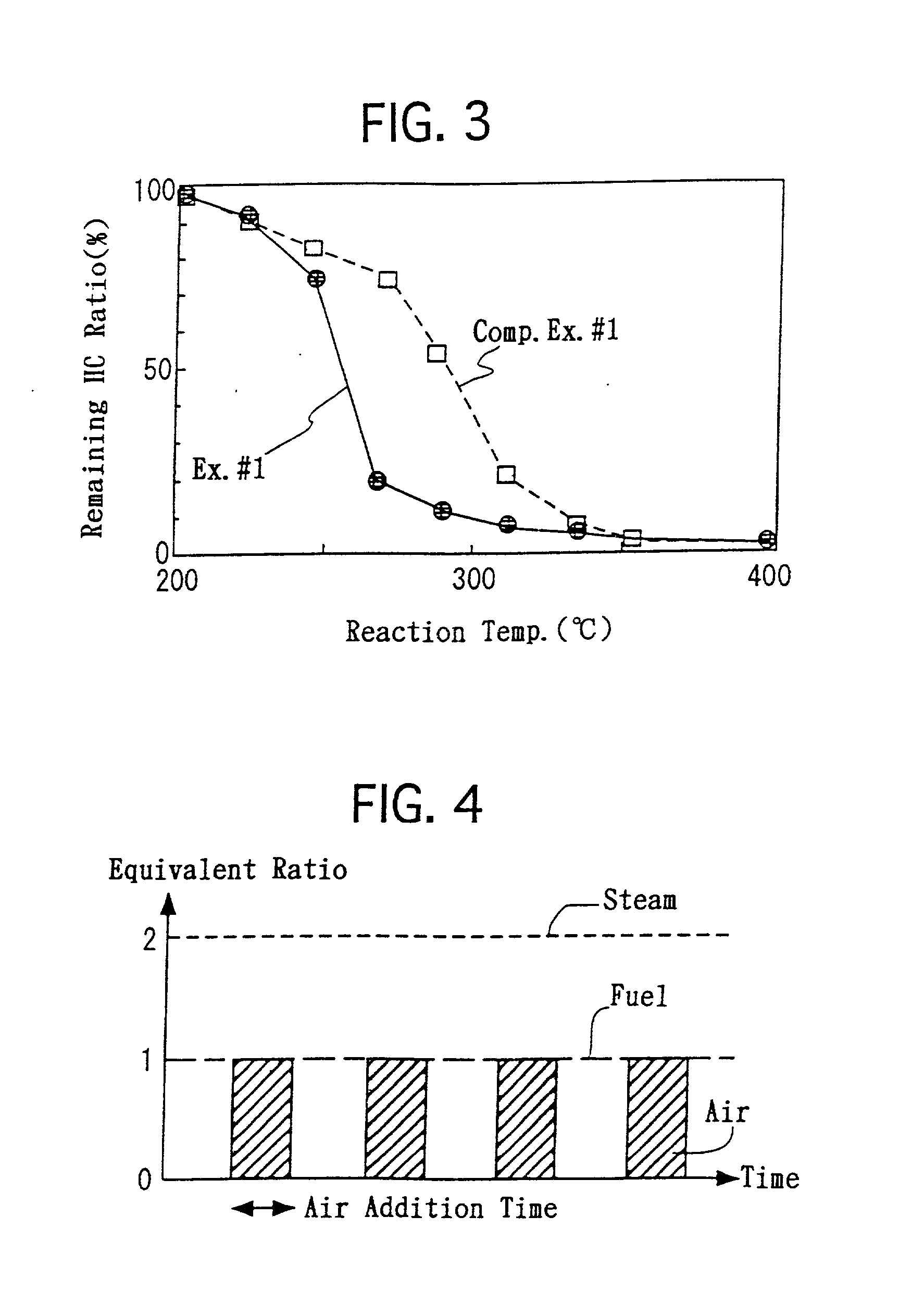
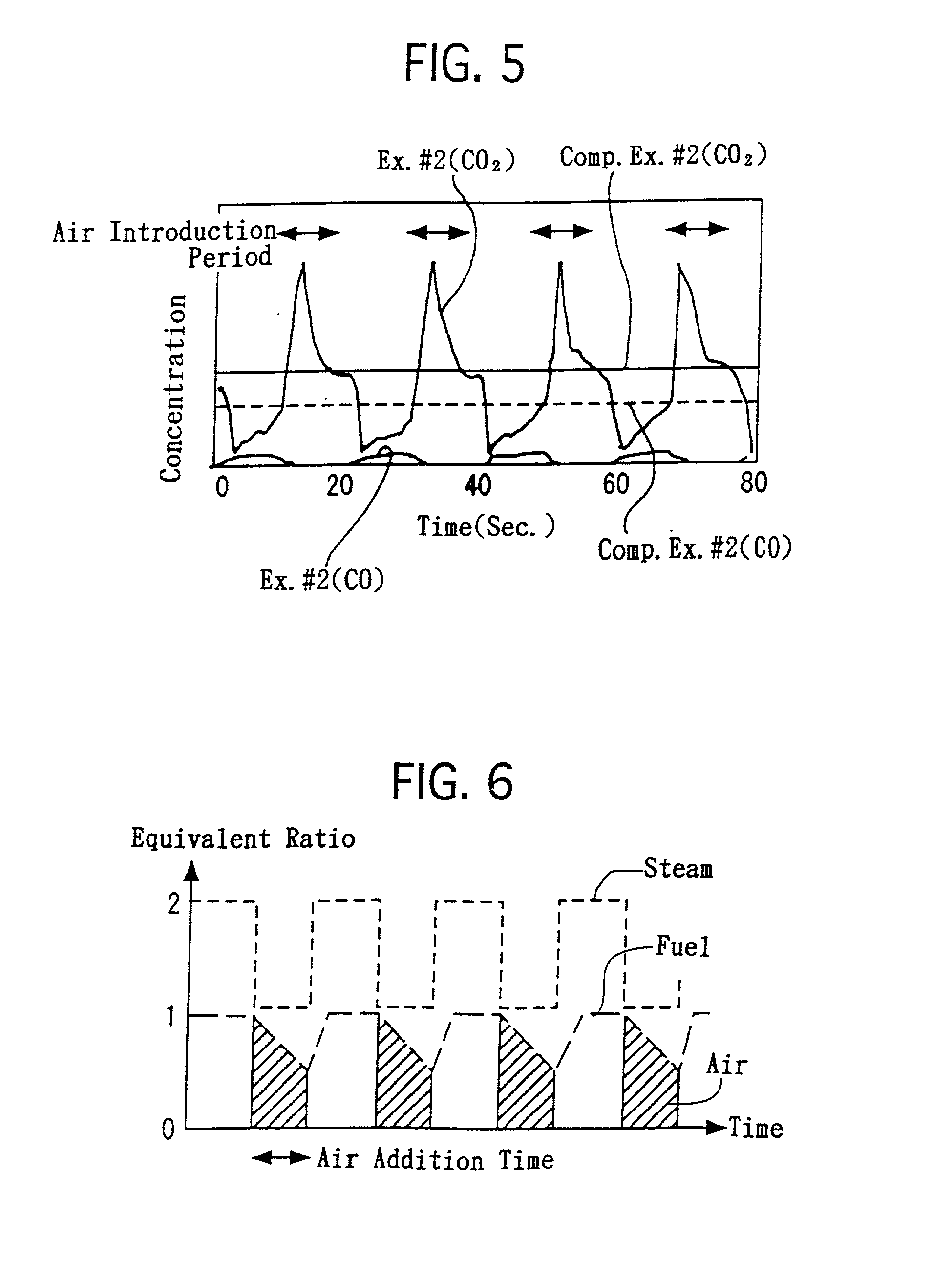
[0084] The honeycomb-shaped substrate, which was provided with the reactor bed, was disposed in the reactor 3. As illustrate in FIG. 4, the following operations were repeated at 350.degree. C. alternately. Specifically, propylene and steam were supplied for 10 seconds under the condition that the molar H.sub.2O / C ratio was controlled at 2.0. Thereafter, in addition to the propylene and steam, air was supplied for 10 seconds in an equivalent amount for completely combusting the propylene. At the outlet of the reactor 3, the CO concentrations and CO.sub.2 concentrations in the outlet gas were measured continuously. FIG. 5 illustrates the results.

example no.3

EXAMPLE NO. 3

[0087] In the above-described hydrogen generation process of Example No. 2, the supplying amounts of the propylene and steam were constant. However, when carrying out the heating step, it is not necessary to supply the steam. Moreover, in the heating step, the propylene can be supplied sufficiently in such an amount that only a heat quantity, which enables CaCO.sub.3 to decompose, is provided. Accordingly, it is possible to reduce the propylene supply amount less in the heating step than that in contacting step.

[0088] Hence, in Example No. 3, the steam and fuel were supplied as illustrated in FIG. 6. Specifically, the steam supply amount was reduced by half when the air was supplied. The fuel supply amount was reduced gradually as the time periods of the air supply elapsed, and was reduced by half at 10 minutes after the air supply started.

[0089] Therefore, in accordance with the hydrogen generation process of Example No. 3, it was possible to reduce the usage amounts o...


PUM

PropertyMeasurementUnit
temperatureaaaaaaaaaa

Abstract

A contacting step, in which a mixture gas, including a fuel and steam, is contacted with a reactor bed, including a reforming catalyst and a carbon dioxide adsorbent, thereby converting the mixture gas into hydrogen and adsorbing co-generating carbon dioxide onto the carbon dioxide adsorbent, and a heating step, in which the reactor bed is heated, thereby desorbing the adsorbed carbon dioxide from the carbon dioxide adsorbent and regenerating a carbon dioxide adsorption capacity thereof, are carried out alternately. The resulting CO is converted into H2 and CO2, and the converted CO2 is absorbed by the carbon dioxide adsorbent and is adsorbed outside the equilibrium system. Accordingly, methane is inhibited from co-generating. Hence, the reformed fuel gas is mostly composed of H2 and is free from methane, and the reaction temperature limitation, i.e., from 700 to 900° C., in the steam reforming reaction is not applicable any more.

Description

[0001] 1. Field of the Invention[0002] The present invention relates to a process for generating hydrogen and an apparatus for generating hydrogen, process and apparatus which can sharply reduce an amount of co-generating carbon monoxide (CO). The hydrogen, which is generated in accordance with the present invention, can be appropriately used as a raw material for synthesizing ammonia, for an automotive fuel cell, or the like.[0003] 2. Description of the Related Art[0004] As a conventional process for generating hydrogen, a process has been known in which a steam reforming reaction is utilized. In the steam reforming reaction, hydrocarbons, such as petroleum, and steam are reacted. Since the steam reforming reaction is an equilibrium reaction, the higher the reaction temperature is, or the lower the steam concentration is, the lower the hydrogen generation ratio. On the other hand, the lower the reaction temperature is, the higher the methane generation ratio.[0005] The aforemention...

Claims


Application Information

Patent Timeline
Patent Type & Authority Applications(United States)
IPC IPC(8): B01D53/02B01J8/02B01J19/24C01B3/38
CPCB01D53/02B01J8/0285B01J19/2485B01J2208/00309B01J2208/00433B01J2208/00672B01J2208/025B01J2219/00117B01J2219/00139C01B3/38Y02C10/08Y02C20/40Y02P20/151
Inventor YOKOTA, KOJI
Owner TOYOTA CENT RES & DEV LAB INC
Why Eureka
Try Eureka