Optical fiber chromatic dispersion distribution measuring apparatus and measuring method

a technology of optical fiber and chromatic dispersion, which is applied in the direction of optical apparatus testing, instruments, optical elements, etc., can solve the problems of difficult to specify the far end of the optical fiber under test, complicated configuration of the apparatus, and decrease in measurement sensitivity

Inactive Publication Date: 2002-07-11
YOKOGAWA ELECTRIC CORP
View PDF16 Cites 5 Cited by
  • Summary
  • Abstract
  • Description
  • Claims
  • Application Information

AI Technical Summary

Benefits of technology

0057] According to a sixth aspect of the invention, there is provided the method according to the fifth aspect of the invention, further comprising the steps of adjusting both wavelengths of the two light beams so that wavelength of the one of the four-wave mixing light beams coincides with a center wavelength of an optical bandpass filter having a fixed center wavelength for executing the extracting step. Therefore, position of the far end of the optical fiber can be easily determined by using the normal optical time domain reflectometer (OTDR) without using a bandpass filter having a variable center wavelength.

Problems solved by technology

However, due to a mechanical structure of the optical bandpass filter having the variable center wavelength, a loss caused by inserting the optical bandpass filter having the variable center wavelength is more than 10 dB to decrease the measurement sensitivity.
In case of compensating the loss, which is caused by inserting the optical bandpass filter having the variable center wavelength, by using an optical amplifier, the configuration of the apparatus becomes complicate.
Therefore, it is problem that the far end of the optical fiber under test is difficult to be specified.

Method used


Image

  • Optical fiber chromatic dispersion distribution measuring apparatus and measuring method
  • Optical fiber chromatic dispersion distribution measuring apparatus and measuring method
  • Optical fiber chromatic dispersion distribution measuring apparatus and measuring method

Examples


Embodiment Construction

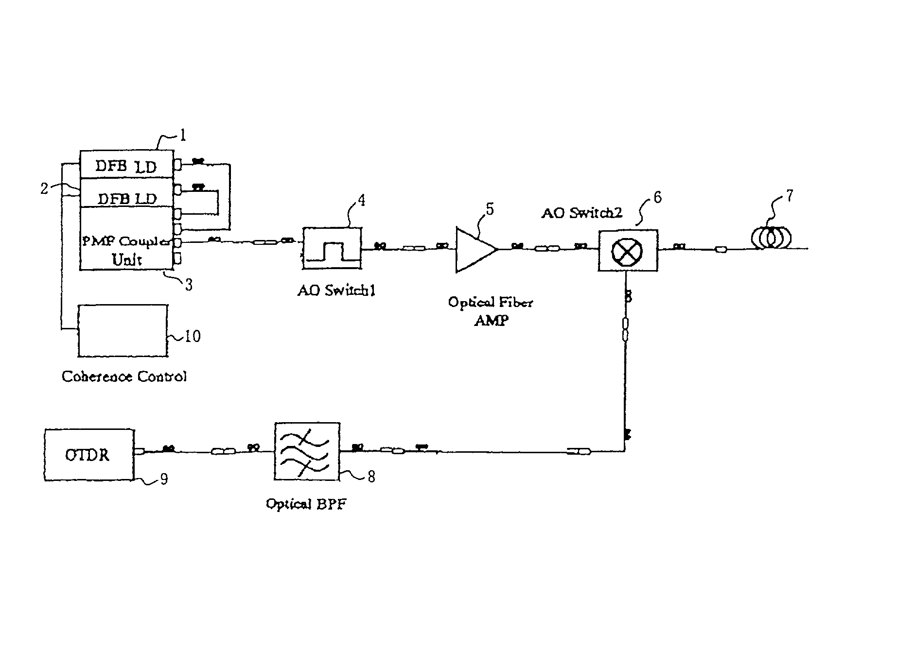
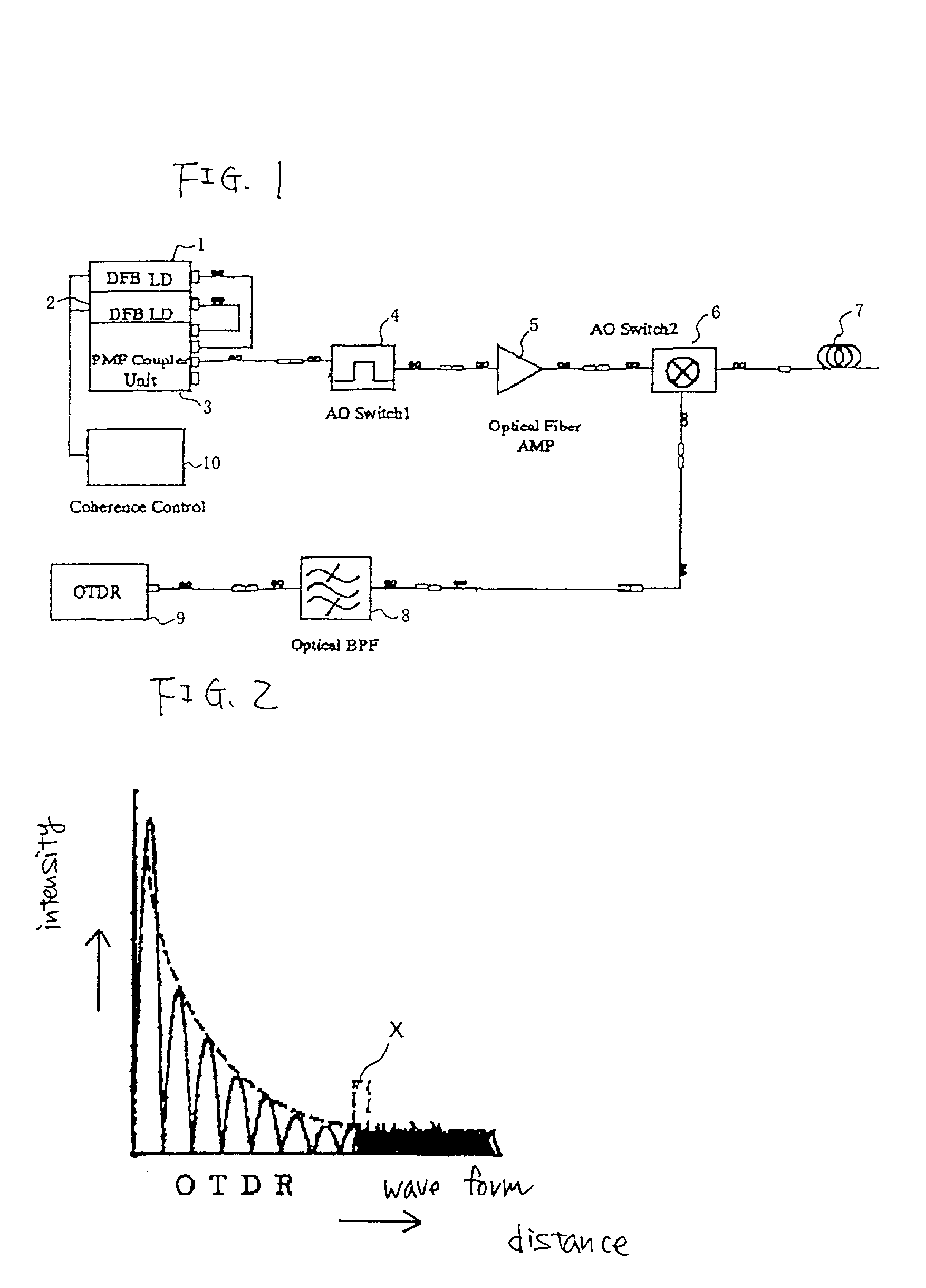
[0062] An optical fiber chromatic dispersion distribution measuring apparatus according to the invention will be given with reference to FIG. 1.

[0063] In FIG. 1, reference numeral 1 denotes a first light source (distributed feedback laser diode (DFB LD)), reference numeral 2 denotes a second light source (DFB LD), and reference numeral 3 denotes an optical coupler (Polarization Maintaining Fiber (PMF) Coupler Unit) for combining a plurality of light beams.

[0064] Reference numeral 4 denotes an acousto-optic element (first acousto-optic (AO) switch), reference numeral 5 denotes an optical fiber amplifier (Optical Fiber AMP), reference numeral 6 denotes a directional coupler (second acousto-optic (AO) switch, reference numeral 7 denotes a optical fiber under test, reference numeral 8 denotes an optical bandpass filter (Optical BPF), and reference numeral 9 denotes an optical time domain reflectometer (OTDR).

[0065] Also, reference numeral 10 is a coherence controller for controlling coh...


PUM

PropertyMeasurementUnit
insertion lossaaaaaaaaaa
chromatic dispersion distributionaaaaaaaaaa

Abstract

An optical fiber chromatic dispersion distribution measuring apparatus for measuring the chromatic dispersion distribution of an optical fiber under test comprising two light sources 1, 2 at least one of which can change wavelength thereof, wherein light beams having different wavelengths from each other and emitted from the two light sources are inputted to the optical fiber under test 7 to measure a four-wave mixing light beam generated by interaction between the two light beams by optical time domain reflectometer (OTDR) 9; wherein an optical bandpass filter 8 having a fixed center wavelength is provided at a previous stage of the optical time domain reflectometer (OTDR); and wherein a coherence controller 10 for controlling coherence of at least one of the light beams outputted from the two light sources 1, 2.

Description

[0001] 1. Filed of the Invention[0002] The present invention relates to an optical fiber chromatic dispersion distribution measuring apparatus for measuring the chromatic dispersion distribution of an optical fiber and a measuring method.[0003] 2. Description of the Related Art[0004] It is known that when two pulse light beams having different wavelengths .lambda..sub.1, .lambda..sub.2 from each other are simultaneously inputted to an optical fiber under test, four-wave mixing light beams are generated due to interaction between the two inputted pulse light beams.[0005] A relation among the wavelengths .lambda..sub.1, .lambda..sub.2 of the pulse light beams and wavelengths .lambda..sub.3, .lambda..sub.4 of the four-wave mixing light beams is shown in FIG. 2.[0006] In FIG. 2, the longitudinal axis indicates the wavelength of each of light beams and the transverse axis indicates the intensity of each of light beams. Symbols a and b indicate the pulse light beams having the wavelength ...

Claims


Application Information

Patent Timeline
Patent Type & Authority Applications(United States)
IPC IPC(8): G01M11/02G01M11/00
CPCG01M11/3163
Inventor AOKI, SHOICHINAGASHIMA, SHINYA
Owner YOKOGAWA ELECTRIC CORP
Why Eureka
Try Eureka