Burner for high-temperature combustion

a burner unit and high-temperature technology, applied in the direction of combustion types, greenhouse gas reduction, combustion using lumps and pulverulent fuels, etc., can solve the problems of high cost of raw materials and fabrication aspects, refractory materials, ceramic or metallic materials, etc., and achieve low cost, reduce the amount of energy transmitted, and efficient insulation

Inactive Publication Date: 2002-07-11
MAINE MICRO FURNACES
View PDF0 Cites 10 Cited by
  • Summary
  • Abstract
  • Description
  • Claims
  • Application Information

AI Technical Summary

Benefits of technology

0018] It is possible to control or modulate the temperature of the burner wall by varying the mass flow rate and composition of the cooling medium, e.g by changing the ratio of water vapor to carbon dioxide, or by introducing other constituents to the cooling medium stream, or by regulating the incoming temperature of the gaseous cooling medium, or by a combination of these factors.
0019] Because it is possible to maintain the temperature of the burner tube with the annular stream of cooling medium, it becomes unnecessary to provide for cooling of the burner tube from its outside. A burner according to the present invention can have a burner tube that is efficiently insulated (such as with a vacuum jacket or other heat insulating medium), and force the heat of combustion to be carried by the gaseous cooling medium.
0020] It is an object of the present invention to reduce the amount of energy transmitted to the walls of a burner, so that a given burner may be operated at a higher combustion temperature than it could be, without the gaseous curtain.
0021] It is an object of the present invention to provide a low cost apparatus for performing high temperature incineration.
0022] It is a further object of the present invention to enable the combustion of fuels using nearly pure oxygen, in order to minimize the production of oxides of nitrogen.

Problems solved by technology

Refractory materials, whether ceramic or metallic, tend to be more costly from both raw material and fabrication aspects, than commonly fabricated materials such as low alloy steels.

Method used


Image

  • Burner for high-temperature combustion
  • Burner for high-temperature combustion
  • Burner for high-temperature combustion

Examples


Embodiment Construction

[0064] In one embodiment, the burner of the present invention comprises a hollow cylindrical burner tube and a cap for the discharge of fuel, oxidizer and the gaseous cooling medium to the interior of the hollow burner tube.

[0065] It is not necessary that the burner tube be cylindrical, and various shapes may prove advantageous, depending on the materials and fabrication methods appropriate for those materials, as well as to suit various combustion reactions.

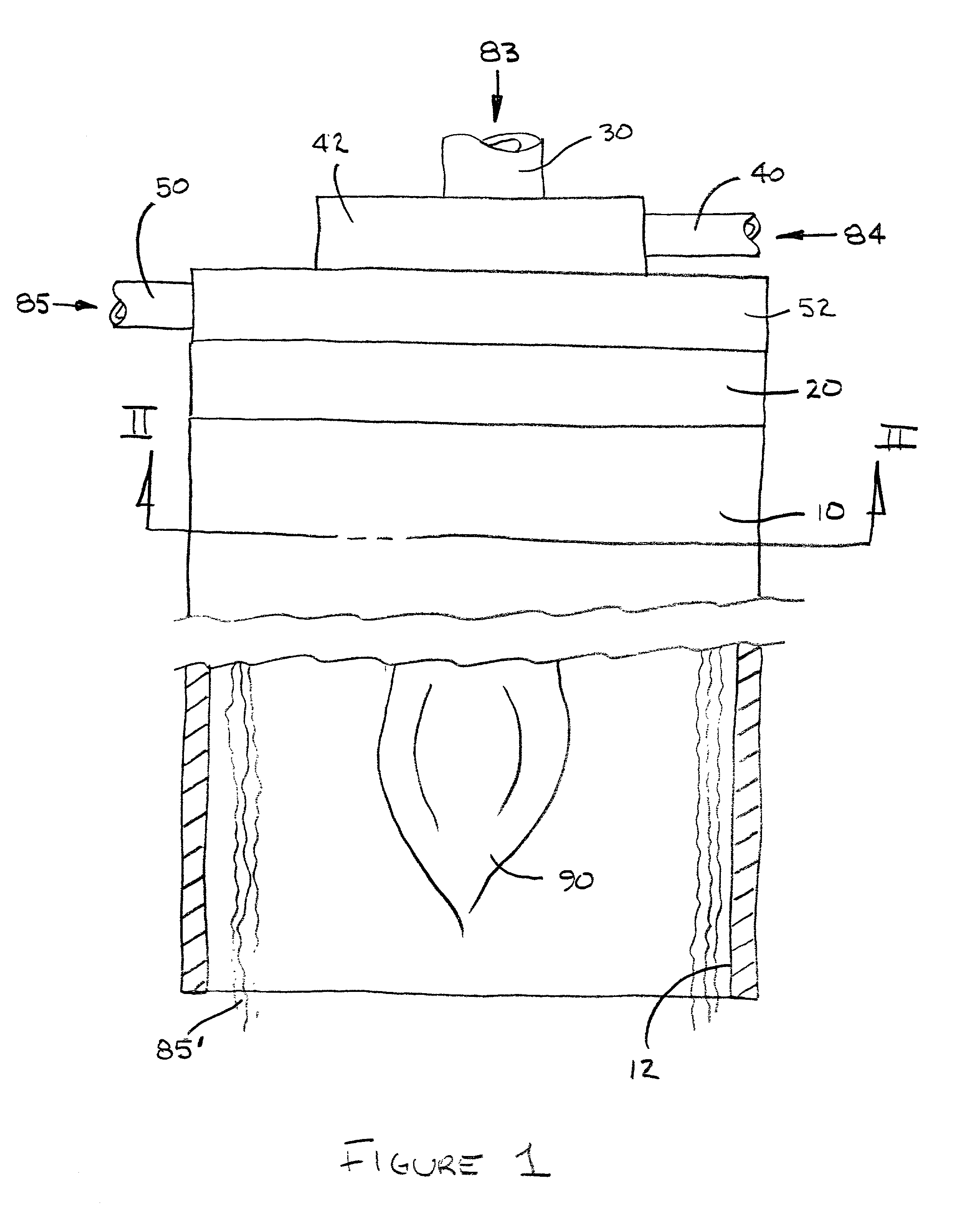
[0066] FIG. 1 is a partially cutaway elevation view of a burner unit of one embodiment according to the present invention.

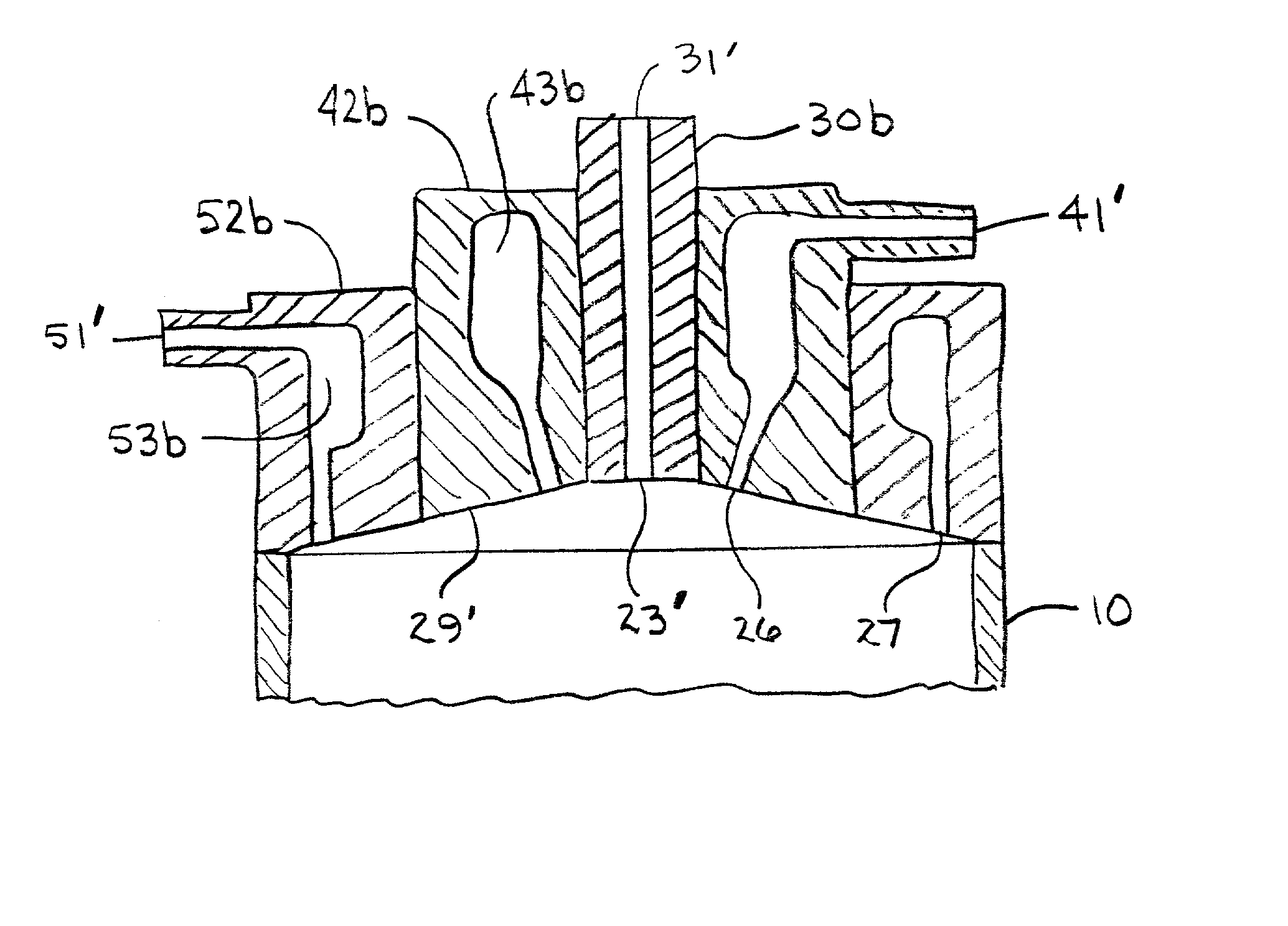
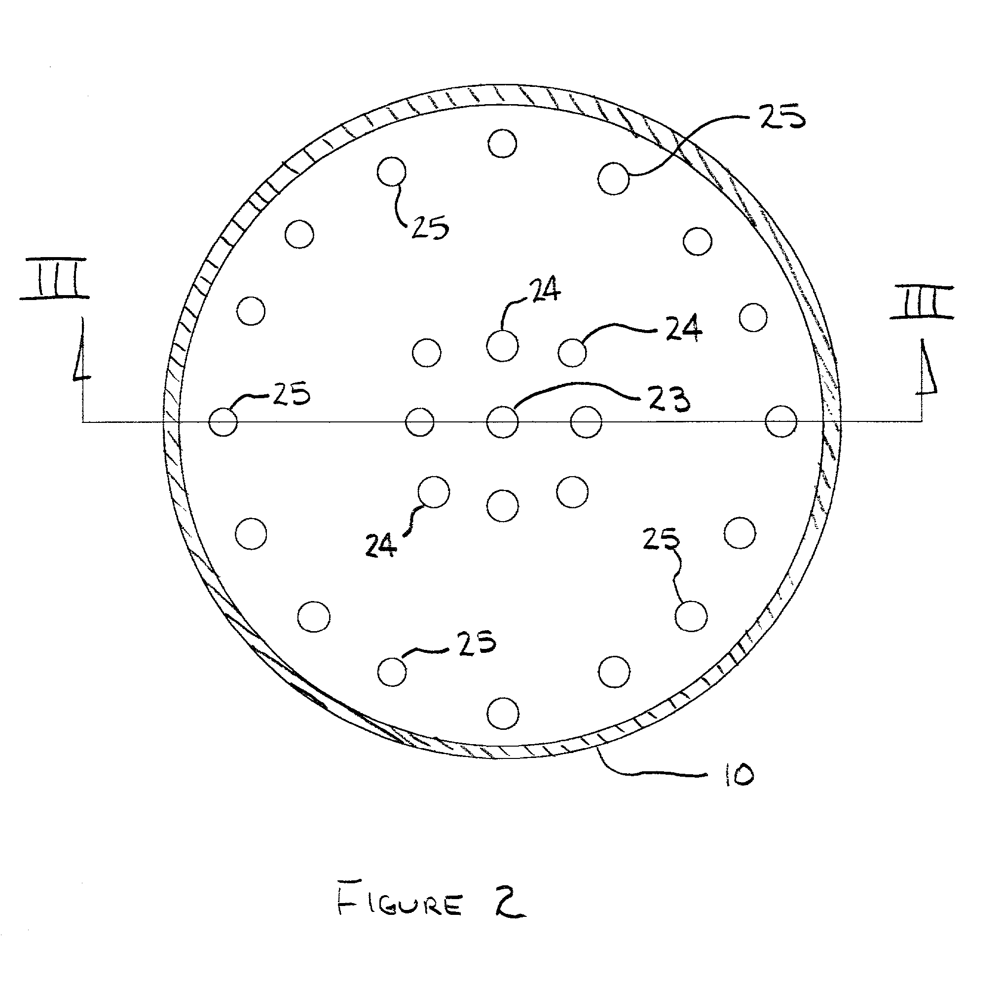
[0067] The burner is made up of hollow cylindrical burner tube 10 that will contain the combustion reaction and burner cap 20 that has openings for the introduction of fuel, oxidizer and cooling medium to the inside of the burner tube. Burner cap 20 comprises means 30 for delivering fuel 83, means 40, 42 for the delivery of an oxidizer 84, and means 50, 52 for the delivery of the cooling medium 85.

[0068] The ...


PUM


Abstract

A high-temperature burner is provided that is suited for the incineration of shredded plastics, tires, carpet or similar materials. The burner walls are protected from the heat of the ongoing combustion reaction by an annular curtain of water vapor or carbon dioxide that takes the radiant heat energy of the high-temperature combustion reaction. The annular curtain removes the heat energy from the vicinity of the burner walls before the energy can be conveyed to them. Higher temperature combustion can be attained without resorting to jacketed burner construction or the use of refractory materials.

Description

BACKGROUND OF THE PRESENT INVENTION SUMMARY OF THE PRIOR ART[0001] This invention relates to a burner, and more particularly to a burner for high temperature combustion wherein the interior burner wall is protected from the heat of combustion by a primarily gaseous shield, and wherein the gaseous shield is substantially made up of water vapor or carbon dioxide or a combination of water vapor and carbon dioxide.[0002] High temperature combustion reactions are useful, because they encourage the conversion of carbon monoxide to carbon dioxide, the combustion of relatively large organic molecules, and the combustion of "soot." The high temperature combustion reaction results in less production of pollutants than a lower temperature combustion, given the same source of fuel.[0003] The use of burners to produce or contain high temperature combustion reactions is well known, and a variety of methods have been adopted to permit high combustion temperatures. As the temperature of the combust...

Claims


Application Information

Patent Timeline
Patent Type & Authority Applications(United States)
IPC IPC(8): F23D11/36F23D14/78F23D1/00
CPCF23D11/36F23D14/78F23D2214/00Y02E20/366Y02E20/30
Inventor PRIBISH, VINCENT R.
Owner MAINE MICRO FURNACES
Why Eureka
Try Eureka