Transmission device and transmission method

a transmission device and transmission method technology, applied in the direction of digital transmission, amplifier modification to reduce non-linear distortion, baseband system details, etc., can solve the problem of high bit precision, the sacrifice of the conversion speed associated with high bit precision becomes unacceptable, and the phase difference between the feedback signal and the reference signal may be produced in the transmission devi

Inactive Publication Date: 2002-07-25
FUJITSU LTD
View PDF11 Cites 40 Cited by
  • Summary
  • Abstract
  • Description
  • Claims
  • Application Information

AI Technical Summary

Benefits of technology

[0023] In this way, a digital input signal and a compensating signal are converted separately by means of a first digital / analog converter and a second digital / analog converter, respectively. This obviates the need for a digital / analog converter having high bit precision, as would be needed to convert a predistorted digital input signal to an analog signal. Accordingly, faster conversion is possible.
[0025] In this way, the distortion-compensating signal generator generates a compensated signal in which only nonlinear distortion produced by the amplifier is compensated. This allows the distortion-compensating signal generator to reliably compensate nonlinear distortion produced by the amplifier. Further, since the second digital / analog converter is supplied only with a signal in which nonlinear distortion produced by the amplifier has been compensated, bit precision can be lower than when the signal has been compensated for another phase difference, making conversion faster to a corresponding degree.
[0031] In this way, in addition to the initial phase control performed by the first phase difference compensator, phase control is performed during operation of the transmission device to transmit a required transmission signal, enabling phase tracking to compensate phase differences during operation.

Problems solved by technology

However, as distortion-compensated signals typically have greater amplitude than do the same signals prior to compensation, digital-to-analog conversion of compensated signals requires a DAC with high bit precision (i.e., a large number of bits).
Wireless communications systems developed in recent years, particularly systems using high frequency signals--such as communications systems in CDMA base stations--require DACs that can perform conversion rapidly, and in such systems the sacrifice of conversion speed associated with high bit precision becomes unacceptable.
Another drawback is that a phase difference between the feedback signal and reference signal may be produced in the transmission device due to factors such as delay caused by the length of the transmission path of the feedback signal or phase jitter in the local oscillator that performs band conversion (frequency conversion) of the signal.
The presence of a phase difference may make it impossible to perform compensation properly.

Method used


Image

  • Transmission device and transmission method
  • Transmission device and transmission method
  • Transmission device and transmission method

Examples


first embodiment

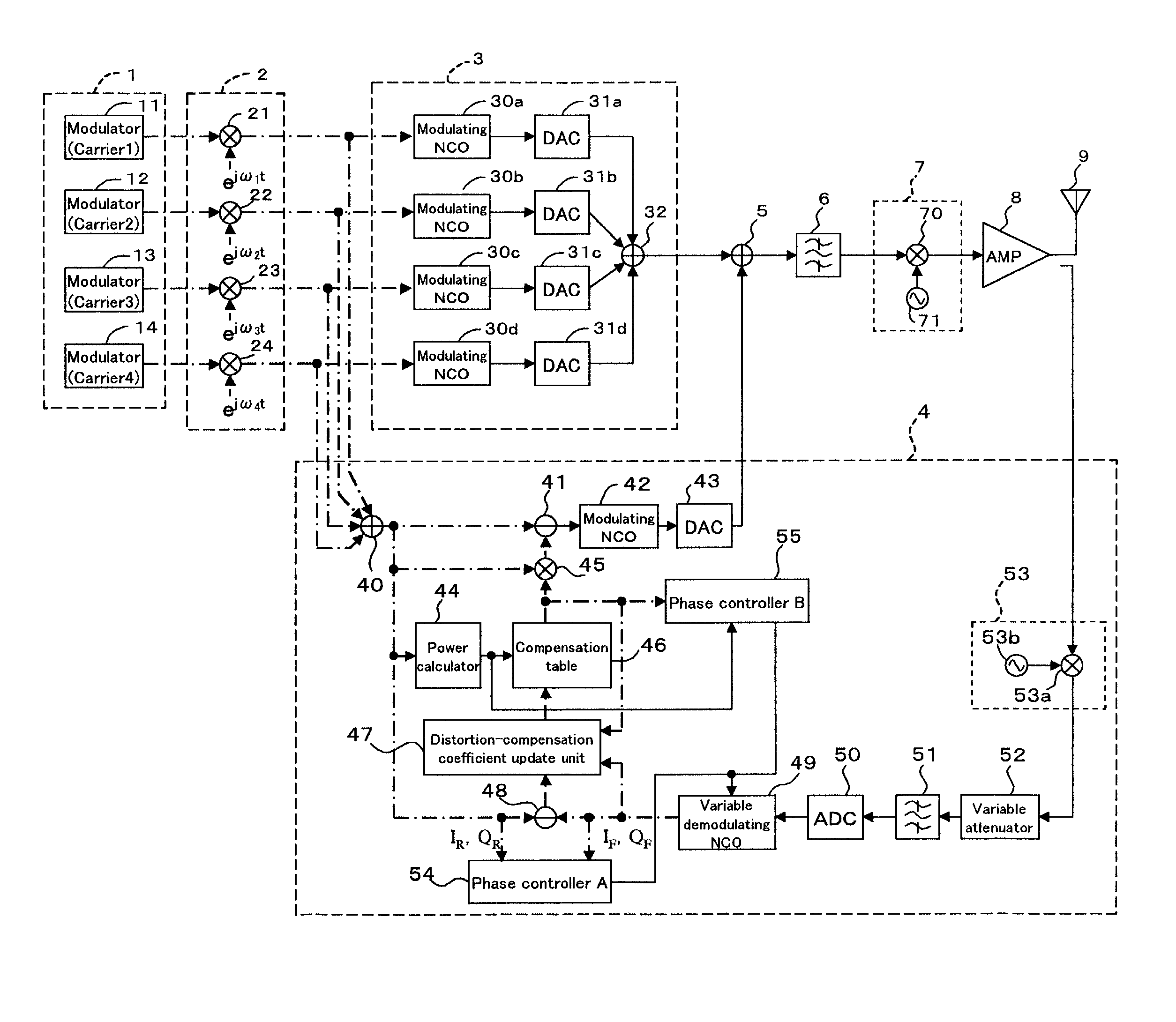
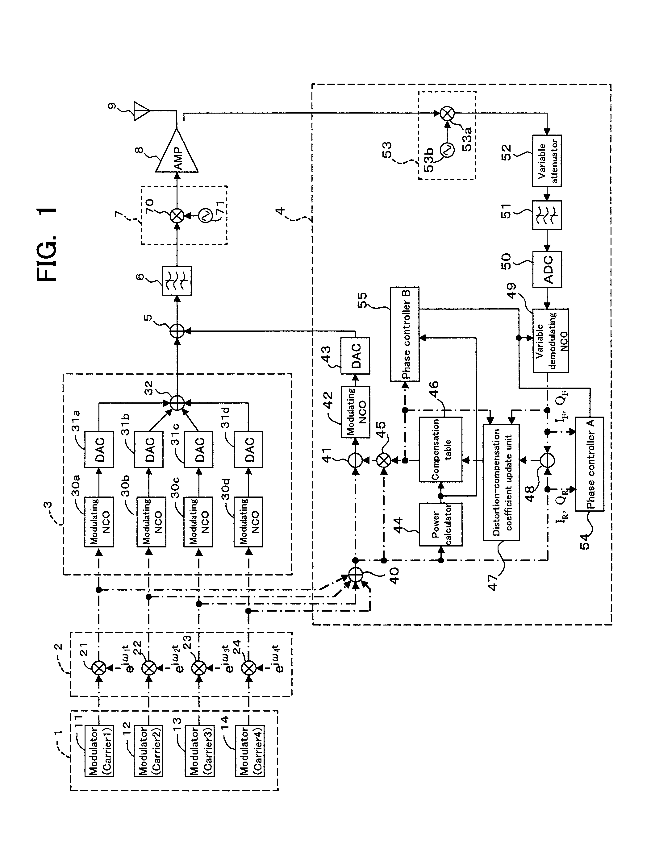
[0051] FIG. 1 is a block diagram depicting an exemplary transmission device according to the invention.

[0052] In the drawing, signal lines are represented by either solid lines or broken lines. Each signal line represented by a broken line is actually composed of two signal lines (for simplicity these are represented by a single broken line) that carry the transmission signals input to the transmission device, namely, the digital "I" channel Ich and the digital "Q" channel Qch, respectively. However, the signal line represented by a broken line output from the compensation table 46 is composed of two signal lines that respectively carry a distortion-compensation coefficient h.sub.I (real part of the distortion-compensation coefficient) and a distortion-compensation coefficient h.sub.Q (imaginary part of the distortion-compensation coefficient). signal lines represented by solid lines, on the other hand, are each composed of one signal line for carrying one signal wherein the digital...

second embodiment

[0105] SECOND EMBODIMENT

[0106] Phase control by the phase controllers A and B in the first embodiment may be performed during quadrature modulation by the modulating NCOs 30a to 30d, rather than being performed by the quadrature demodulating NCO 49. In this second embodiment, phase is controlled during quadrature modulation in this manner.

[0107] FIG. 6 is a block diagram showing the main signal converter 3 of a transmission device pertaining to this second embodiment. In this second embodiment the modulating NCOs 30a to 30d are replaced by variable modulating NCOs 35a to 35d. While not shown in the drawing, the variable quadrature demodulating NCO 49 in the first embodiment is replaced with a demodulating NCO for performing quadrature demodulation and frequency conversion with a phase from which the .DELTA..theta. variable component has been eliminated (or a phase wherein .DELTA..theta.=0). Other components are analogous to those in the transmission device of the first embodiment de...

third embodiment

[0109] THIRD EMBODIMENT

[0110] The analog section phase difference occurring in the feedback signal can also be compensated by additionally providing a shifting multiplier for shifting the phase of the feedback signal.

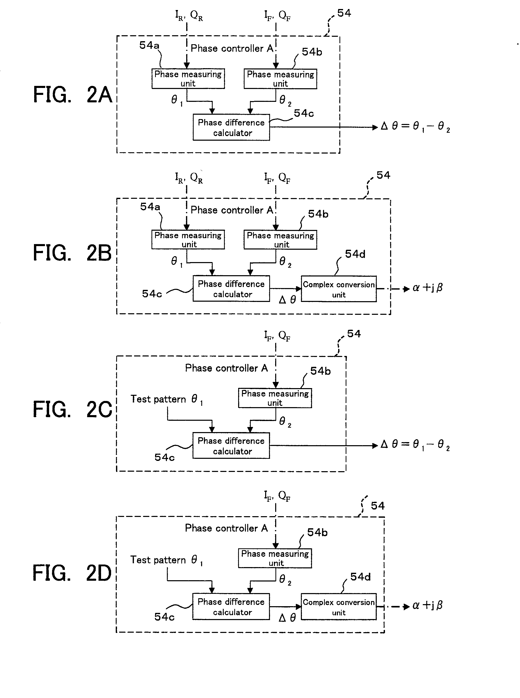
[0111] FIG. 7 is a block diagram showing a portion of a transmission device additionally provided with a shifting multiplier 100 located between the demodulating NCO 490 (the variable demodulating NCO 49 of the first embodiment is replaced with one having non-variable phase) and the subtracter 48. FIG. 2B is a block diagram showing the arrangement of phase controller A for controlling the amount of shift by the shifting multiplier 100, and FIG. 4B is a block diagram showing the arrangement of the phase controller B for controlling the amount of shift by the shifting multiplier 100.

[0112] The phase controller A shown in FIG. 2B is analogous to the phase controller A shown in FIG. 2A, except for being additionally provided with a complex conversion unit 54d. This complex ...


PUM


Abstract

The present invention provides a transmission device for predistorting a digital signal in order to compensate distortion, then amplifying and transmitting it. A digital input signal is converted to a first analog signal by a first D / A converter. Separately, the digital input signal is also subjected to predistortion. A compensating signal is then generated from the digital input signal and the predistorted signal. The compensating signal generated thereby is converted into a second analog signal by a second D / A converter. The first analog signal and second analog signal are then added, this addition operation giving a compensated analog transmission signal. This analog transmission signal is supplied to the amplifier for amplification, and then transmitted via an antenna.

Description

[0001] 1. Field of the Invention[0002] The present invention relates to a transmission device and transmission method for amplifying and transmitting an analog signal that has been converted from a digital input signal, and in particular relates to a transmission device and transmission method for predistorting a digital signal in order to compensate distortion, then amplifying and transmitting it.[0003] 2. Description of the Related Art[0004] As out-of-band power emission in wireless communications systems is regulated, such systems are equipped with linearizers (distortion compensating devices) in order to minimize out-of-band power emission into surrounding channels due to non-linearity of the amplifiers that amplify signals for transmission. FIG. 13 is a block diagram of an exemplary transmission device in a conventional wireless communications system.[0005] This transmission device has a predistortion linearizer that includes a multiplier 210, a power calculator 211, a compensa...

Claims


Application Information

Patent Timeline
Patent Type & Authority Applications(United States)
IPC IPC(8): H03M1/66H03F1/32H04B1/04H04L5/06H04L27/01
CPCH03F1/3247H04L5/06
Inventor KUBO, TOKUROODE, TAKAYOSHINAGATANI, KAZUOHAMADA, HAJIMEISHIKAWA, HIROYOSHIOISHI, YASUYUKIFUDABA, NOBUKAZU
Owner FUJITSU LTD
Why Eureka
Try Eureka