
Method of manufacturing preform for compounding use

a manufacturing method and compounding technology, applied in the direction of metal-working apparatus, braking discs,foundry moulds, etc., can solve the problems of increasing the amount of deformation of the preform after the sintering process, increasing the manufacturing cost of the preform 11, and increasing the time required for sucking the mixtur

Inactive Publication Date: 2002-08-29
MAZDA MOTOR CORP
View PDF0 Cites 8 Cited by
  • Summary
  • Abstract
  • Description
  • Claims
  • Application Information

AI Technical Summary

Benefits of technology

[0012] According to the above-mentioned method, the average of the lengths of the short fibers is set to a smaller value in order to restrain formation of a larger non-reinforced region in a compounded portion. In order to restrain deformation of the preform due to the shorter fibers during the sintering process, the amount of the binder is balanced with the sintering temperature. In consequence, the strength of the preform may be well maintained while the deformation of the preform may be prevented.
[0013] In the above-mentioned method, it is preferable that whiskers are added to the mixture in the step of mixing. If so, the whiskers as the skeleton of the preform improve the strength of the preform. Further, the ceramic particles may be better dispersed.
[0014] In the above-mentioned method, it is also preferable that the ceramic particles include particles having a first average diameter and particles having a second average diameter, which is smaller than the first average diameter. In that case, the particles having the second average diameter may be effectively interposed between the short fibers and the particles having the first average diameter so that the degree of sintering of the preform may be improved as a whole.

Problems solved by technology

Hereupon, if the lengths of the alumina short fibers are smaller, there may be such a tendency that the time required for sucking the mixture extremely increases while the amount of deformation of the preform after the sintering process may increases.
On the contrary, if the lengths of the alumina short fibers are longer, each of the components in the mixture is non-uniformly dispersed so that larger non-reinforced regions may be formed in the compounded portion.
Further, the manufacturing cost of the preform 11 may be increased due to the expensive aluminum borate whiskers while the void content of the preform 11 is lowered.
On the other hand, if the average is larger than 10 .mu.m, it may become hard to sinter the filter cake because the surface energy of the particles is lowered.
In consequence, it may become hard that the molten metal impregnate into the preform 11 when the compounding process is preformed.
On the contrary, if longer whiskers with larger diameters are used, it may become hard that the materials are uniformly mixed together when the slurry is prepared.
In consequence, the SiC particles are non-uniformly dispersed in the compounded portion.
However, if the lengths of the alumina fibers are too short, there occurs such a disadvantage that the alumina fibers cannot sufficiently accomplish their role to constitute the skeleton of the preform.
If the volumetric percentage of the materials to be compounded is lifted to 40 %, it may become extremely difficult to compound the materials.
Further, there is such a tendency that the shorter the average length becomes, the larger the strain (i.e. deformation) becomes.
However, if so, the preform cannot have sufficient strength.
Hereupon, when the sintering temperature is higher than 1100.degree. C., there is such a tendency that the strength of the preform increases steeply.

Method used


Image

  • Method of manufacturing preform for compounding use
  • Method of manufacturing preform for compounding use
  • Method of manufacturing preform for compounding use

Examples


Embodiment Construction

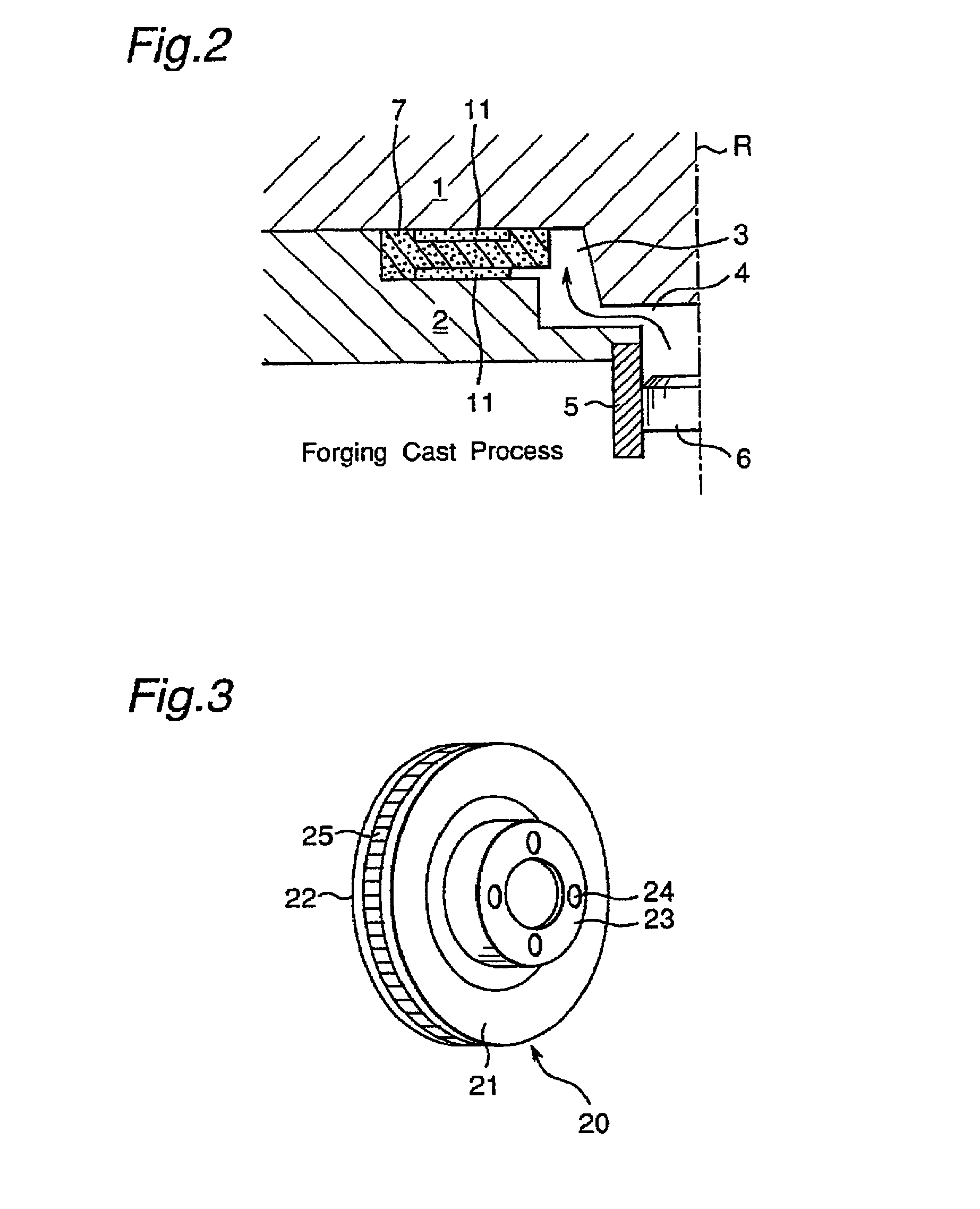
[0076] Hereinafter, an example of the process for compounding the a preform according to the present invention will be described. In this example, a forging cast process is utilized. In the process, the molten metal is composed of aluminum alloy provided by the JIS standard as AC4C. The molten metal having the temperature of 780.degree. C. is pressed up to about 30.4 MPa, and then filled into the casting die with the filling rate of 40 mm / sec. Hereupon, the temperature of the preform is 700.degree. C. The preform has been manufactured using alumina fibers whose average length is 115.4 .mu.m (i.e. alumina fibers II described above).

[0077] The sand core used in this example is a resin coated shell core having the following properties.

4 Ratio of resin: 2.1-2.3 mass % Deflection force: about 6.5 MPa Grain size (AFS): 65-75 Average particle diameter: 0.15 mm

[0078] The sand core is produced by sintering the materials at the temperature of 300 to 320.degree. C., blowing the same for 3 seco...


PUM

PropertyMeasurementUnit
Temperatureaaaaaaaaaa
Fractionaaaaaaaaaa
Fractionaaaaaaaaaa

Abstract

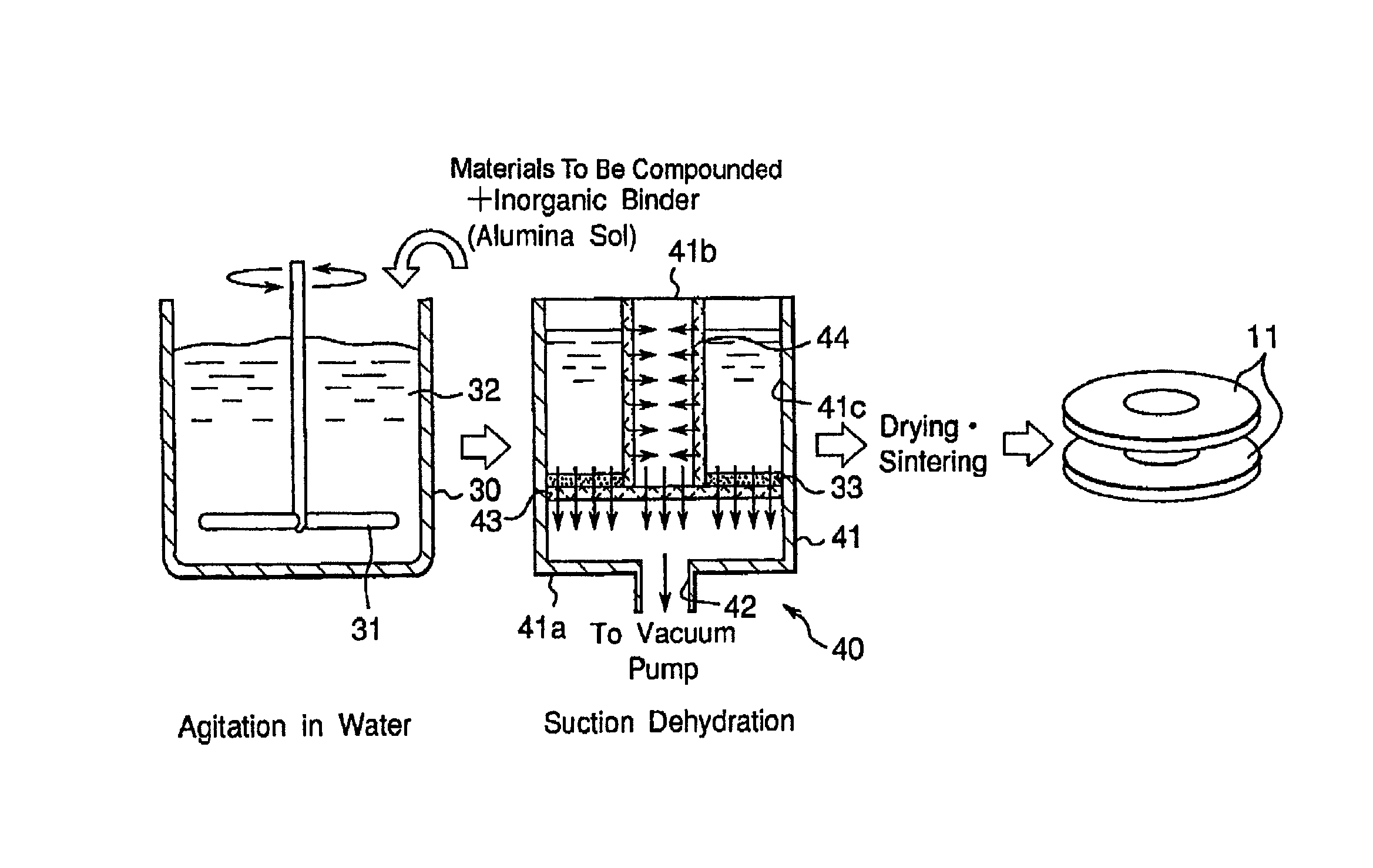
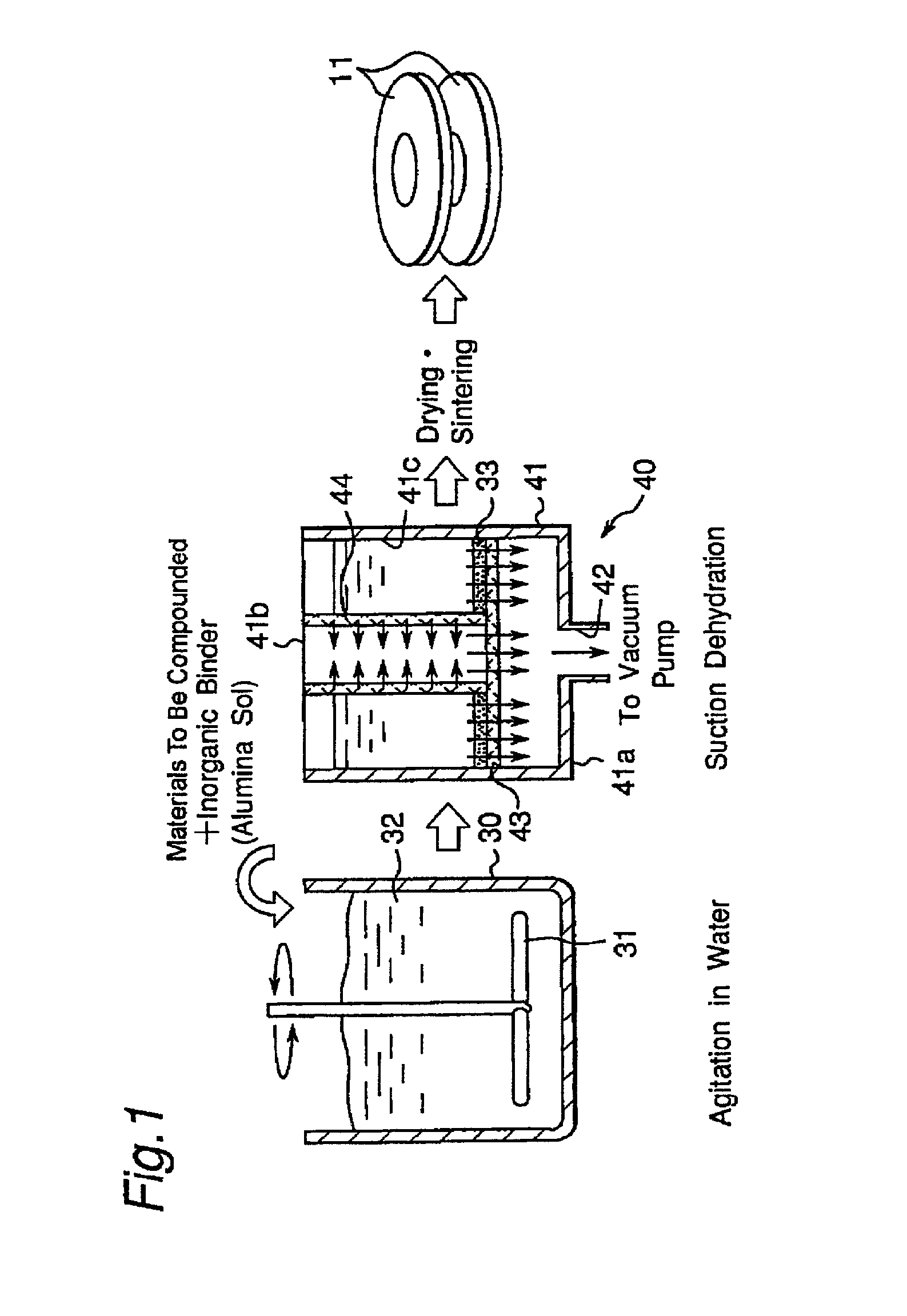
A method of manufacturing a preform for compounding use which, is to be impregnated with a molten metal to be compounded with a matrix material, is provided. The method includes the step of mixing short fibers, ceramic particles and a binder material together to make a mixture. The average of lengths of the short fibers is 100 to 200 mum while the volumetric percentage of the short fibers is 1 to 7 %. The content of the binder material in the mixture is 0.3 to 5.0 mass %. The method includes also the steps of forming the mixture so as to have a predetermined shape, and sintering the mixture at a temperature of 1000 to 1150° C. to form the preform. Thus, it is restrained that the preform is deformed or an un-reinforced region is formed in the compounded portion.

Description

[0001] This application is based on the application No. 2000-287375 filed in Japan, the contents of which are hereby incorporated by reference.[0002] 1. Field of the Invention[0003] The present invention relates to a method of manufacturing a preform for compounding use, which is used, for example, in a casting process for making a brake disk rotor.[0004] 2. Description of the Prior Art[0005] When a brake disk, which is one of parts constituting an automobile, is produced using an aluminum alloy by means of a casting process, the heat resistivity or wear resistance (i.e. anti-wear performance) of a sliding surface of the brake disk is reinforced by the following process. That is, at first, a preform such as a porous ceramic body or the like is disposed in a casting die. Then the preform is impregnated with a molten metal to be compounded with a matrix material.[0006] As a conventional example of the above-mentioned type of preform, Japanese Laid-open Patent Publication No. 7-108370 ...

Claims


Application Information

Patent Timeline
IPC IPC(8): F16D65/12C04B28/00C04B30/02C04B35/80C22C1/10C22C47/14
CPCB22F2998/00B22F2999/00C04B28/00C04B30/02C04B2111/00922C22C47/06C22C2001/1021F16D2250/0007C04B14/303C04B14/305C04B14/324C04B14/383C04B14/4625C04B20/0076C04B40/0268C04B20/006C22C1/1036B22F1/0003B22F1/0014C22C1/1021B22F1/12B22F1/052
Inventor FUJITA, MAKOTO
Owner MAZDA MOTOR CORP
Learn More