Laser cutting apparatus and method

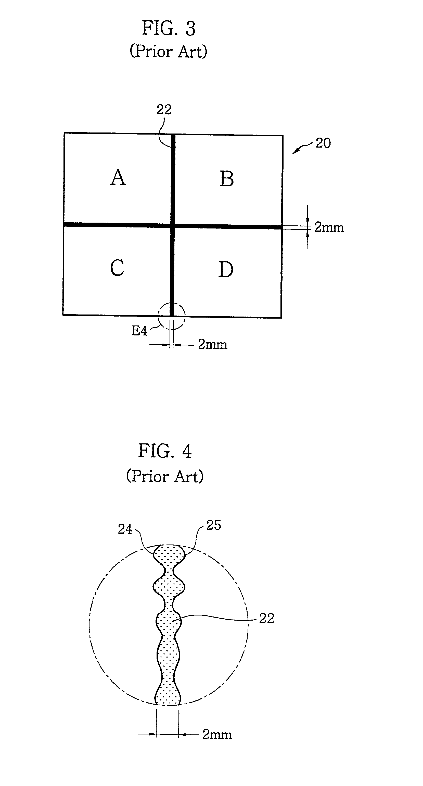
a laser cutting and laser beam technology, applied in the direction of soldering apparatus, instruments, auxiliary welding devices, etc., can solve the problems of cutting out an active area, affecting the cutting efficiency of conventional cutting apparatus using laser beams, and difficult to narrow seam lines 22

Inactive Publication Date: 2002-09-12
SAMSUNG DISPLAY CO LTD
View PDF0 Cites 134 Cited by
  • Summary
  • Abstract
  • Description
  • Claims
  • Application Information

AI Technical Summary

Problems solved by technology

However, a cutting apparatus such as the diamond requires an impact for a complete separation after the preliminary cutting groove is formed, which scatters small glass chips all around the cutting line.
This failure may cut out an active area.
Such a problem occurs frequently while manufacturing a tiled LCD panel for a large screen display.
However, narrowing the seam line 22 is extremely difficult to achieve due to the margin of error when cuffing the LCD unit glass by a diamond cutter.
Therefore, a large tiled LCD module with a low resolution is used for an outdoor projects which do not require a high resolution, despite of its high cost.
A conventional cutting apparatus using a laser beam has following problems.
Another problem is that the LCD unit cell may be spotted and the liquid crystal injection opening of the LCD unit cell may be blocked when the coolant dries up.
Moreover, the coolant sprayed from the cooling unit is splashed, which causes an impediment of the laser cutting apparatus and scattering of the laser beam.
Therefore, a worker cannot see whether the cutting laser beam is proceeding straight along the scribe line.
Therefore, if the cutting laser beam goes out of the scribe line and turns to the inside of the LCD unit cell, the crack is also propagated toward the inside of the LCD unit cell.
Thus, if the scanning line of the laser beam cannot be seen by the worker, all the LCD unit cells cut from the

Method used


Image

  • Laser cutting apparatus and method
  • Laser cutting apparatus and method
  • Laser cutting apparatus and method

Examples


embodiment 1

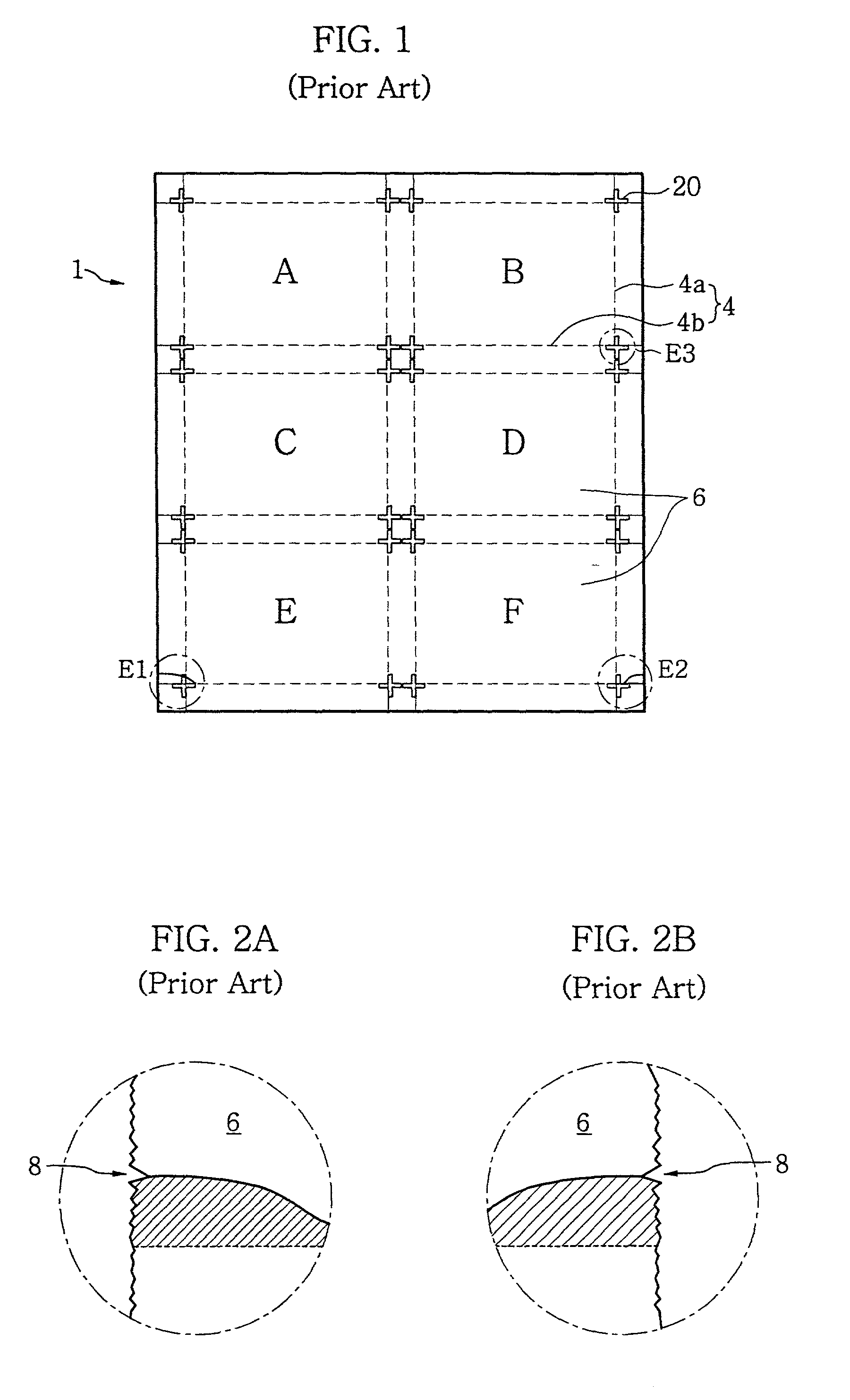
[0170] As described previously, the laser cutter according to the present invention substantially prevents the object from being cut erroneously deviating from the marked cutting line by forming a pre-cut groove at the start edge and the end edge of the cutting line before irradiating the laser beam along the cutting line.

[0171] Also, in case that cutting lines are normal to each other, the laser cutter of the present invention can be used by forming a pre-cut groove at the starting edge of the second cutting line.

[0172] In addition, exact control of irradiation timing of laser beam and the position of pre-cut grooves by the position sensor prevents waste of electric power and coolant.

[0173] Moreover, since it is possible to grind the upper edge of the cut face using laser beam, the static electricity can be prevented during the grinding step.

[0174] In addition, it is possible to round the upper edge of the cut face without an additional grinding step using an elliptic laser beam wi...

first embodiment

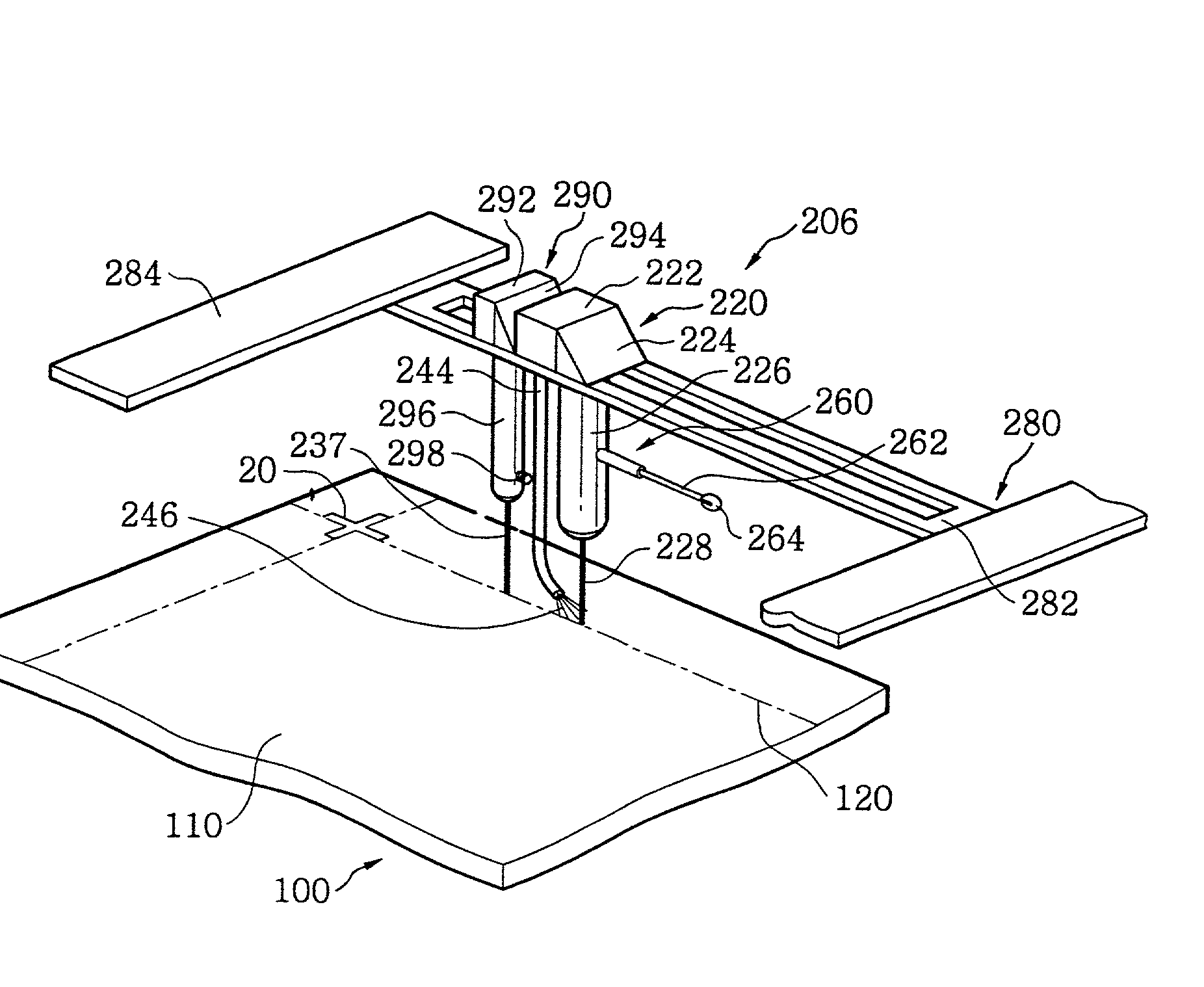
[0177] Here, since constitutions and operations of moving unit 280, laser unit 220, cooling unit 240, and pre-scriber 260 are almost the same as those of the first embodiment, such descriptions are not repeated.

[0178] The coolant inhaler 250 includes an inhaling pipe 254 disposed at the back of a coolant spraying unit 244 with respect to the traveling direction of the laser unit 220 along Y-axis moving plate 282, and a pump 252. The inhaling pipe 254 inhales coolant sprayed onto the cutting line 120 and the pump 252 vacuums the inhaling pipe 254.

[0179] Preferably, one end of the inhaling pipe 254 is bent toward the coolant spraying unit 244 such that the inhaling pipe 254 effectively inhales the sprayed coolant.

[0180] Here, the inhaling power of the pump 252 should be lower than the spraying pressure of the coolant 246, in order to prevent the coolant inhaling pipe 252 from inhaling coolant before it reaches the cutting line headed by the laser beam.

[0181] A method of cutting the gl...

second embodiment

[0196] Thus, according to the present invention, the coolant inhaler is disposed at the back of the cooling unit and inhales the coolant after cooling of the heated scriber line of the substrate, thereby preventing the scattering of the laser beam to improve the cutting power.

[0197] In addition, the laser cutter according to the second embodiment of the present invention prevents the contamination of the substrate and also prevents the liquid crystal inlet hole from being plugged up due to the remaining coolant.

[0198] Meanwhile, although the second embodiment shows and describes that the laser cutter including the laser unit, prescriber, cooling unit, and coolant inhaler moves along the scriber line, it is possible that the cutting process is performed by moving the substrate with the laser cutter fixed.

[0199] In the cooling unit applied to the laser cutters of the first and second embodiments, when the temperature of coolant gas around the scribe line 120 is lower than that of cool...


PUM

PropertyMeasurementUnit
Fractionaaaaaaaaaa
Diameteraaaaaaaaaa
Wavelengthaaaaaaaaaa

Abstract

The present invention disclose a laser cutter for cutting an object being cut such as a two glasses-attached panel for LCD using a laser beam. The laser cutter includes a laser unit for irradiating a laser beam with a specific wavelength along a marked cutting line of the object, a pre-scriber for forming a pre-cut groove at starting edge of the marked cutting line, and a cooling unit for cooling the cutting line which said laser beam has been irradiated.

Description

[0001] (a) Field of the Invention[0002] The present invention generally relates to cutting of a substrate, and more particularly to apparatus and method for cutting a brittle object such as a glass substrate for use of an LCD panel using a laser.[0003] (b) Description of the Related Art[0004] Liquid crystal display (LCD) devices are a well known form of flat panel display. Especially, the smaller, lighter and less power consumptive characteristics make the LCD devices considered as one of the most contending display devices to replace the cathode ray tube (CRT).[0005] LCD devices include two pieces of glass substrates, and a liquid crystal inserted between the two glass substrates. The liquid crystal acts as an optical shutter for an incident light by changing its alignment state by applying an electric field, and thereby an image is displayed on the LCD screen.[0006] To enhance a productivity in manufacturing such LCD devices, methods for making a plurality of panels in a single pr...

Claims


Application Information

Patent Timeline
IPC IPC(8): B23K37/00B23K26/046B23K26/067B23K26/14B23K26/38B23K26/40B28D1/22B28D5/00C03B33/07C03B33/09G02F1/1333H01L21/00
CPCB23K26/045B23K26/046B23K26/0604B23K26/0608B23K26/067B23K26/0736B23K26/0884B23K26/10B23K26/1417B23K26/1458B23K26/365B23K26/367B23K26/4075B23K26/421B23K2201/40B28D1/221B28D5/00B28D5/0076B32B2457/202C03B29/025C03B33/076C03B33/091C03B33/093G02F1/133351H01L21/67092B23K26/127B23K26/40B23K26/044B23K26/146B23K26/1462B23K26/361B23K26/364B23K26/60B23K2101/40B23K2103/50Y02P40/57
Inventor CHOO, DAE-HOKIM, BYEONG-ILLJUNG, SUNG-UKLEE, WOO-SHIKKIM, BURN-SOO
Owner SAMSUNG DISPLAY CO LTD
Why Eureka
Try Eureka