Flat panel display device utilizing electron emission devices

a technology of electron emission device and display device, which is applied in the manufacture of electric discharge tube/lamp, discharge tube luminescnet screen, discharge tube/screen, etc., can solve the problems of bus electrode risk, drawback of destruction in the top electrode, and very thick insulator layer, so as to achieve stable electron emission without deterioration

Inactive Publication Date: 2002-09-12
PIONEER CORP
View PDF0 Cites 21 Cited by
  • Summary
  • Abstract
  • Description
  • Claims
  • Application Information

AI Technical Summary

Benefits of technology

0011] The present invention has been conceived taking the above situation into consideration, and it is an object of the invention to provide a flat panel display device utilizing such electron emission sites capable of providing stable electron emission without deterioration.

Problems solved by technology

As a result, a high resistivity of the thin portion of the top electrode causes an uneven electric field to bring a drawback of destruction in the top electrode.
However, the uneven electric field caused by the thin portion's high resistivity in the top electrode still appears with a risk of breakage of the bus electrode in the case that the thickness of the stacked layers, particularly, the insulator layer is very thick, since no insulating protective film is formed on the backside substrate between the adjacent electron emitting sections.
In such a condition, alkaline components leak from the backside substrate of glass to react with the top electrode directly contacted and then migration and electrode corrosion occur in the top electrode.
As a result, there is a problem that reduction of the electric field to be normally supplied to the electron emitting section of the upper thin-film metal electrode.

Method used


Image

  • Flat panel display device utilizing electron emission devices
  • Flat panel display device utilizing electron emission devices
  • Flat panel display device utilizing electron emission devices

Examples


Embodiment Construction

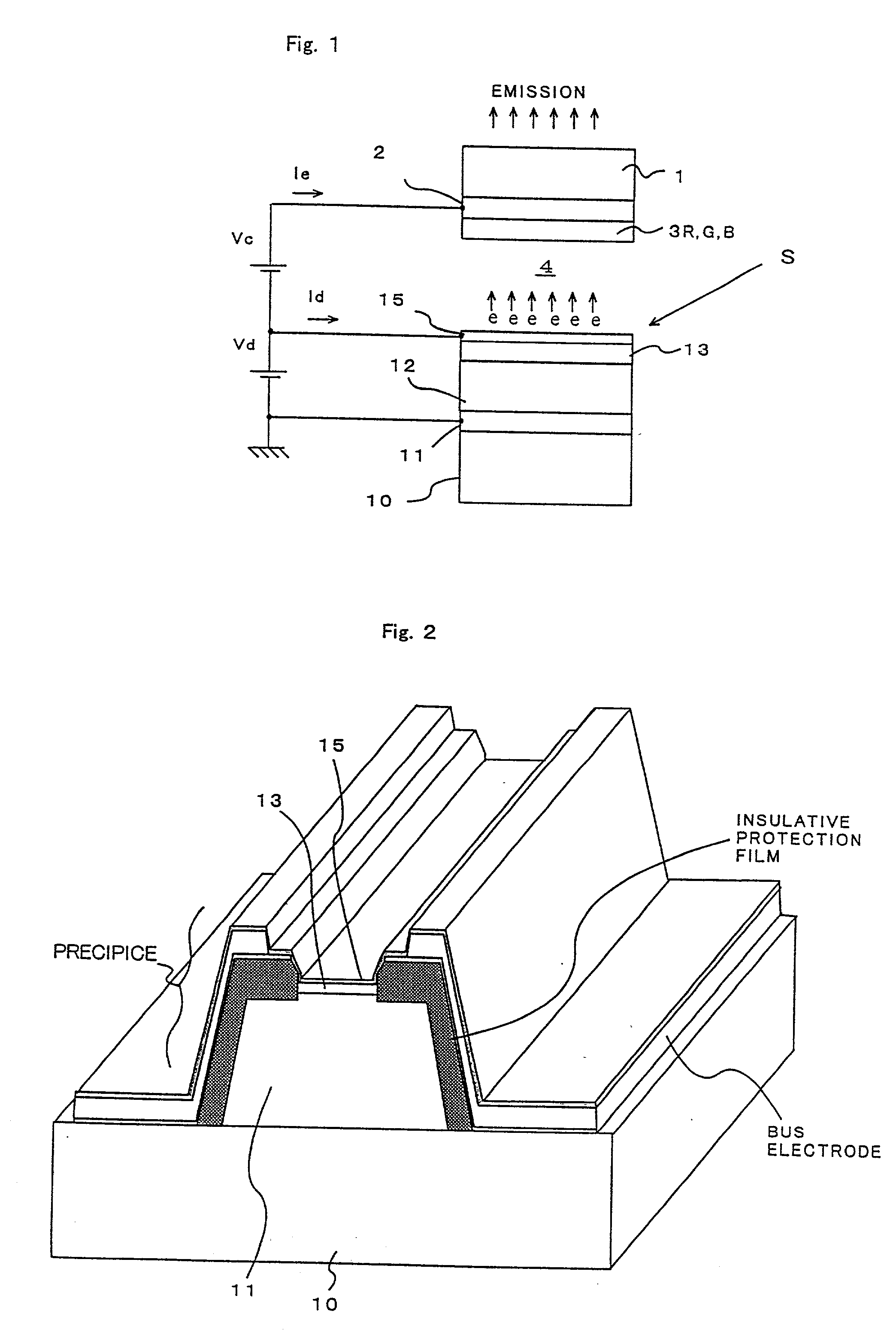
[0064] A flat panel display device was actually fabricated with specifications (1) through (6) as shown below, and then characteristics of the same were examined.

[0065] (1) Bottom electrodes: Cr, Cu, and Cr films having thicknesses of 50 nm, 1 .mu.m, and 100 nm, respectively.

[0066] (2) Semiconductor electron supply layer: Si layer having a thickness of 4 .mu.m.

[0067] (3) Insulator layer: SiO.sub.x layer having a thickness of 330 nm.

[0068] (4) Top electrode: Pt film having a thickness of 40 nm.

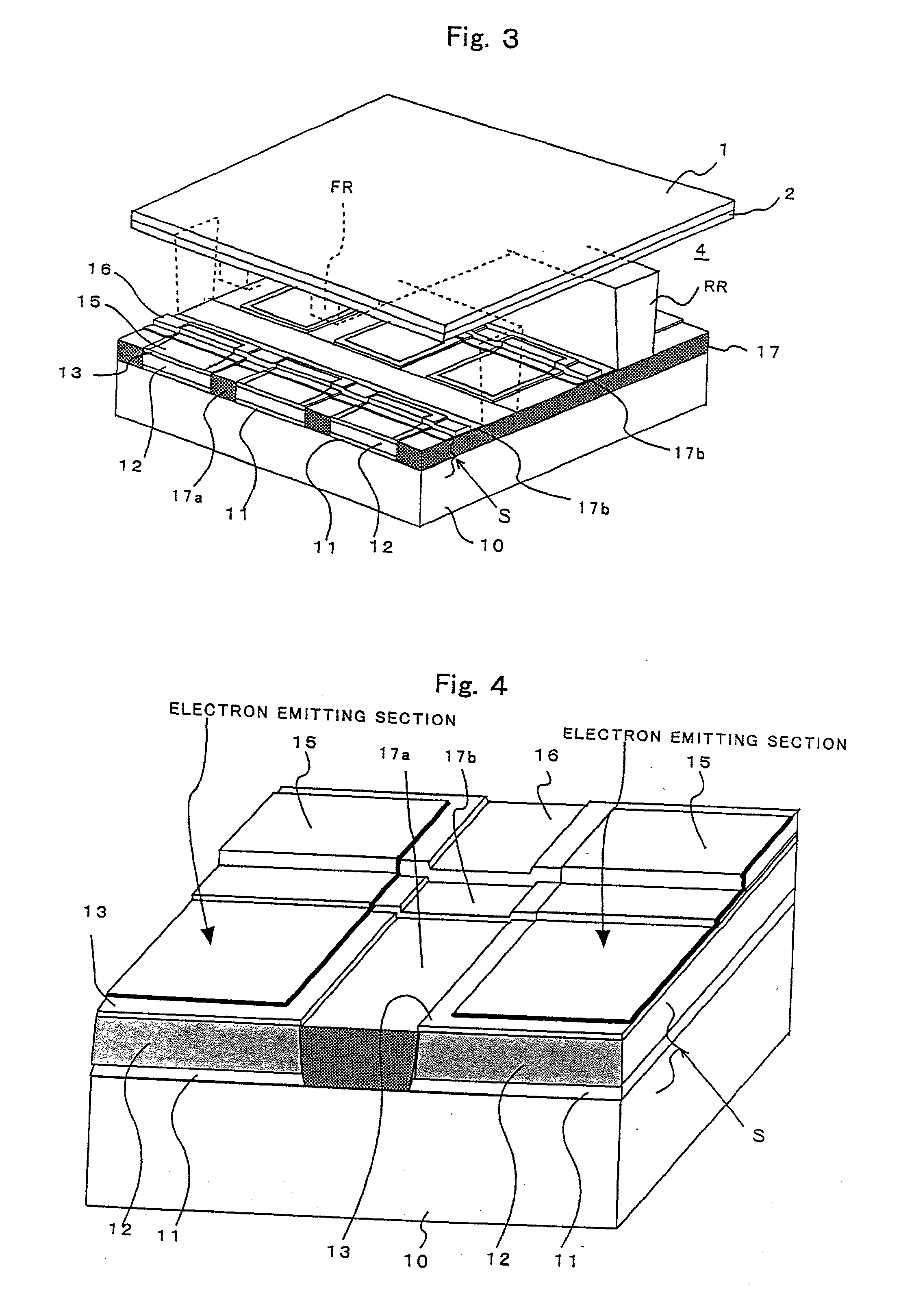
[0069] (5) Bus electrodes: Cr, Cu, and Cr films having thicknesses of 50 nm, 1 .mu.m, and 100 nm, respectively.

[0070] (6) Insulating protective films to be under the bus electrode: SiO.sub.x films having a thickness of 350 nm.

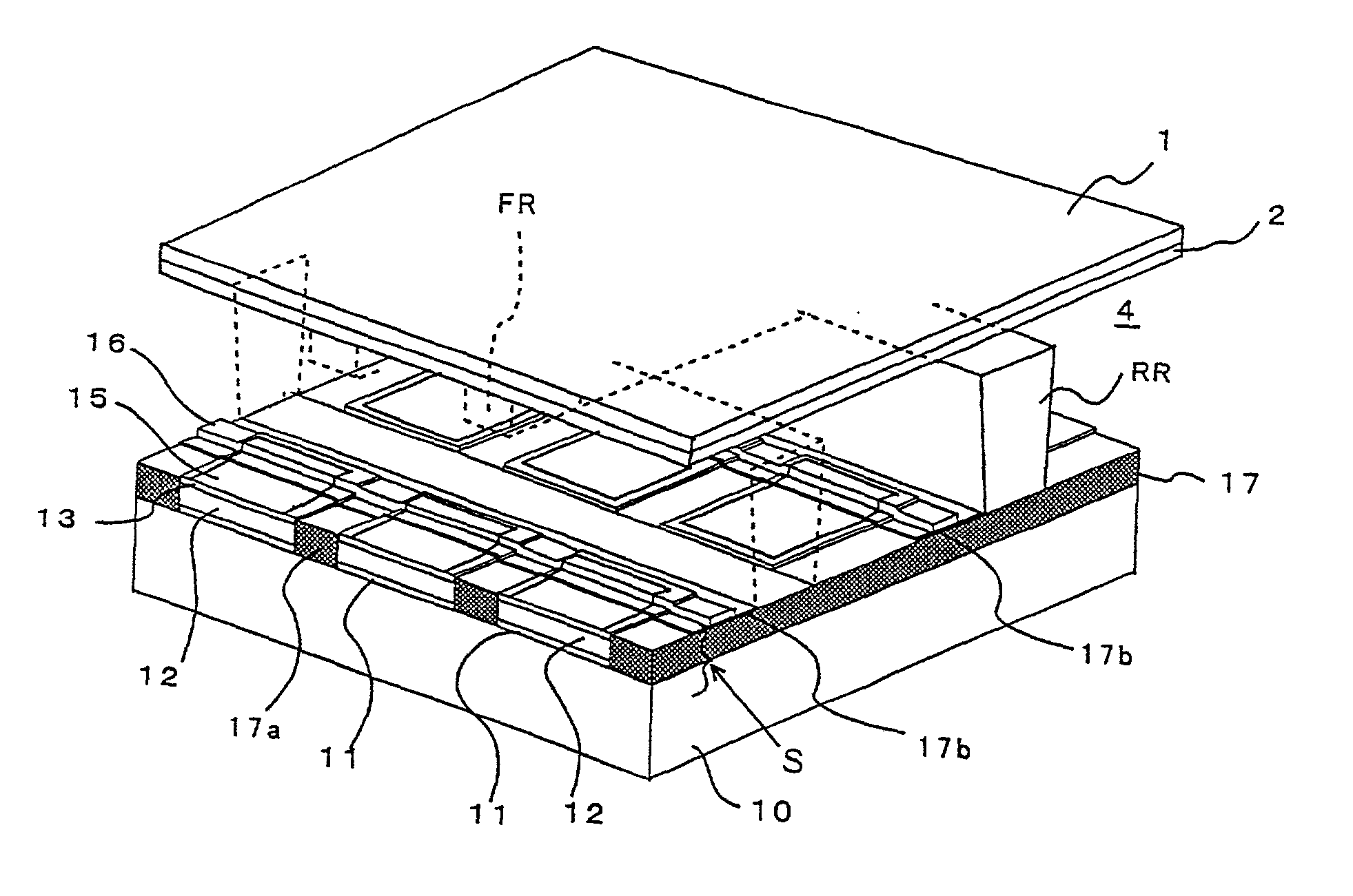
[0071] The bottom electrodes (1) and semiconductor electron supply layers (2) were formed in the form of lines on a glass substrate which had been cleaned. Thereafter, the first insulating protective films to be under the bus electrode (6) were formed between the lines. Ne...


PUM


Abstract

A display device includes a backside and a front-side substrates facing each other with a vacuum space therebetween; and a plurality of electron emission sites provided on the backside substrate. Each electron emission sites includes a bottom electrode formed on a surface of the backside substrate proximate to the vacuum space, an insulator layer formed over the bottom electrode, and a top electrode formed on the insulator layer and arranged individually apart from each other and facing the vacuum space. The display device also includes a plurality of bus electrodes for electrically connecting the neighboring top electrodes; and insulating protective films each provided between the bus electrode and the insulator layer and between the bus electrode and the backside substrate.

Description

[0001] 1. Field of the Invention[0002] The present invention relates to an electron emission device and a display apparatus using the same, especially to a flat panel display apparatus in which a plurality of the electron emission devices are arranged in an image display array, i.e. in a matrix arrangement.[0003] 2. Description of the Related Art[0004] Conventionally, FEDs (field emission display devices) are known as flat type light-emitting display devices having an array of cool-cathode type electron emission sources whose cathodes are not required to be heated. It is necessary to unitize the flat type display device utilizing FEDs to develop an ultra-large display unit system for a next generation. Electron emitting devices as electron emission sources of FEDs include devices having a metal-insulator-semiconductor (MIS) structure and devices having a metal-insulator-metal (MIM) structure.[0005] As shown in FIG. 1, an electron emission device having the MIS structure has a diode ...

Claims


Application Information

Patent Timeline
Patent Type & Authority Applications(United States)
IPC IPC(8): H01J29/04H01J1/312H01J31/12
CPCB82Y10/00H01J1/312H01J31/127H01J2201/3125
Inventor CHUMAN, TAKASHIYOSHIKAWA, TAKAMASAHATA, TAKUYASAKEMURA, KAZUTOYAMADA, TAKASHINEGISHI, NOBUYASUIWASAKI, SHINGOSATOH, HIDEOYOSHIZAWA, ATSUSHIOGASAWARA, KIYOHIDE
Owner PIONEER CORP
Why Eureka
Try Eureka