Inverter and lamp ignition system using the same

a technology of inverter and lamp, which is applied in the direction of dc-ac conversion without reversal, process and machine control, instruments, etc., can solve the problems of increased loss, additional power loss, and limited efficiency of such combination of buck converter and royer inverter, so as to avoid current asymetry and simplify the structure. , the effect of less harmonic composition

Inactive Publication Date: 2002-09-12
HON HAI PRECISION IND CO LTD
View PDF0 Cites 8 Cited by
  • Summary
  • Abstract
  • Description
  • Claims
  • Application Information

AI Technical Summary

Benefits of technology

[0009] It is another object of the present invention to provide an inverter for lamp ignition device, in which the transformer has a simple structure without the provision of a central tap.
[0010] It is a further object of the present invention to provide an inverter for lamp ignition device, which operates at a duty cycle of approximately D=0.5 and is dimmable by burst mode control. Current asymetry is thus avoided.
[0011] It is still a further object of the present invention to provide a lamp ignition system, which outputs to the lamp voltage waves with less harmonic compositions. Therefore, higher illuminating efficiency, longer lifespan of the lamp, and smaller electromagnetic interference are achieved.
[0014] The control circuit comprises a driving circuit which utilizes the voltage across the reset capacitor as driving power for generating two switch control signals respectively output to the first switch transistor and the second switch transistor so as to reduce the conducting resistance thereof.

Problems solved by technology

The efficiency of such combination of a buck converter and a Royer inverter is limited by the two power conversion stages.
Particularly, the magnetizing inductance of the transformer in the Royer DC / AC converter serving as the resonant inductance causes additional power loss.
Especially in the case of a low input voltage, a higher coil ratio of the transformer is required, so that the loss increases and the entire efficiency decreases.
Such transformer structure uses a central tap, and thus is difficult to be miniaturized and has a higher manufacturing cost.
Besides, only one set of the coils operates in each of the half-cycle of the transformer, and the utility rate is accordingly low.
Moreover, the output voltage waves of such inverter have higher harmonic compositions, which cause a lower illuminating efficiency, a shortened lifespan of a lamp, and a greater electromagnetic interference.
In summary, such inverter has the disadvantages of higher manufacturing cost, lower efficiency, and excessive harmonic waves.

Method used


Image

  • Inverter and lamp ignition system using the same
  • Inverter and lamp ignition system using the same
  • Inverter and lamp ignition system using the same

Examples


Embodiment Construction

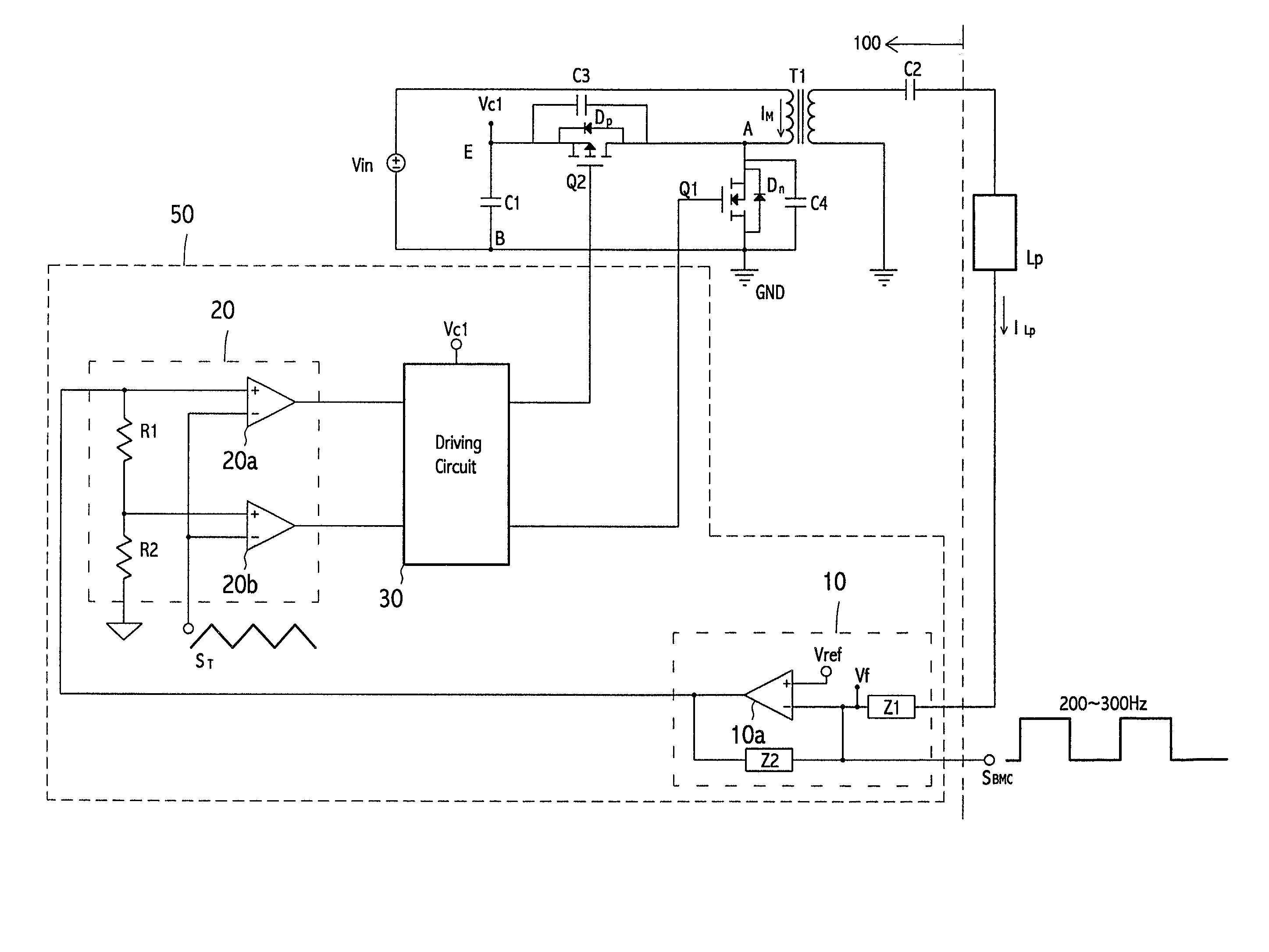
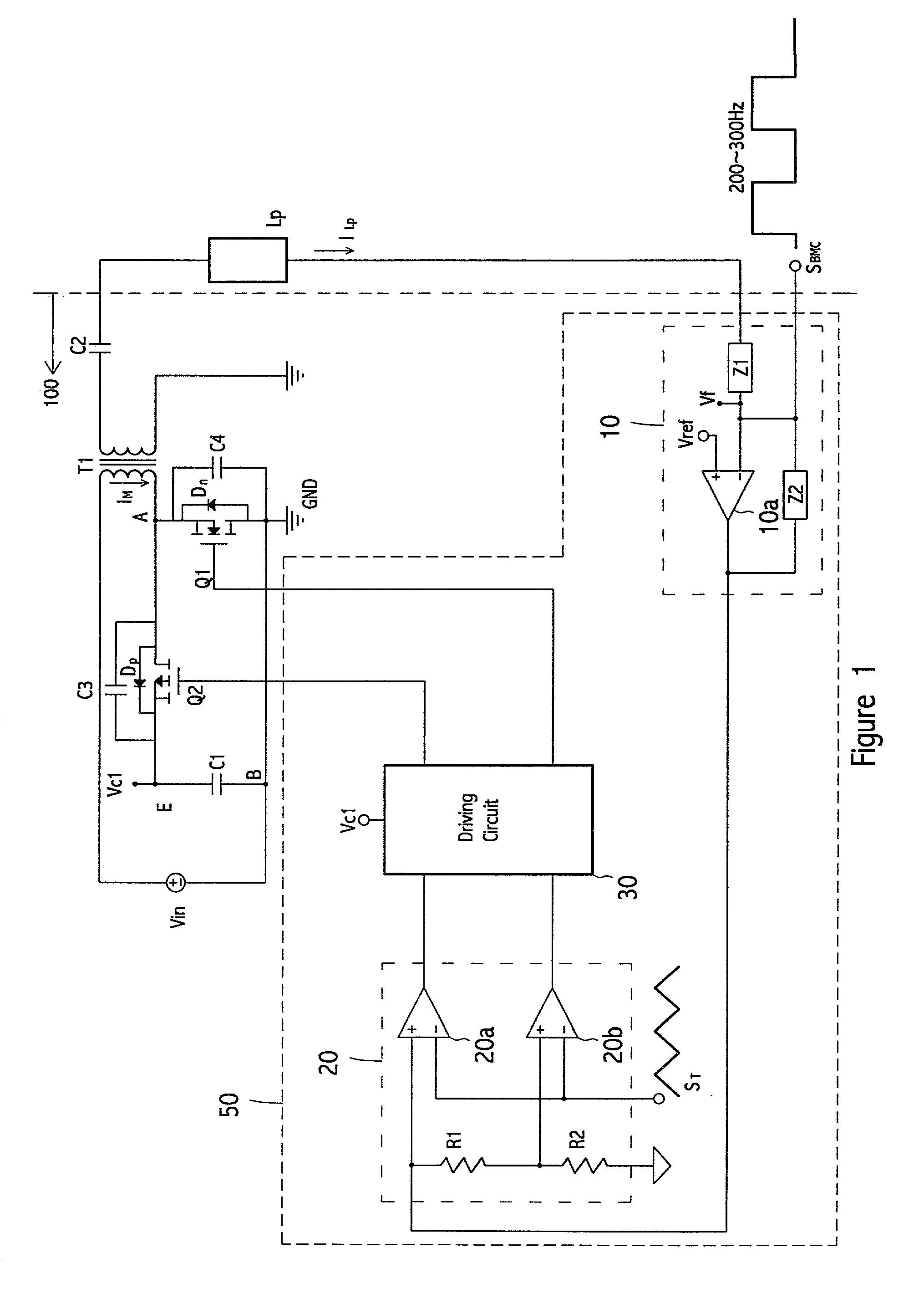
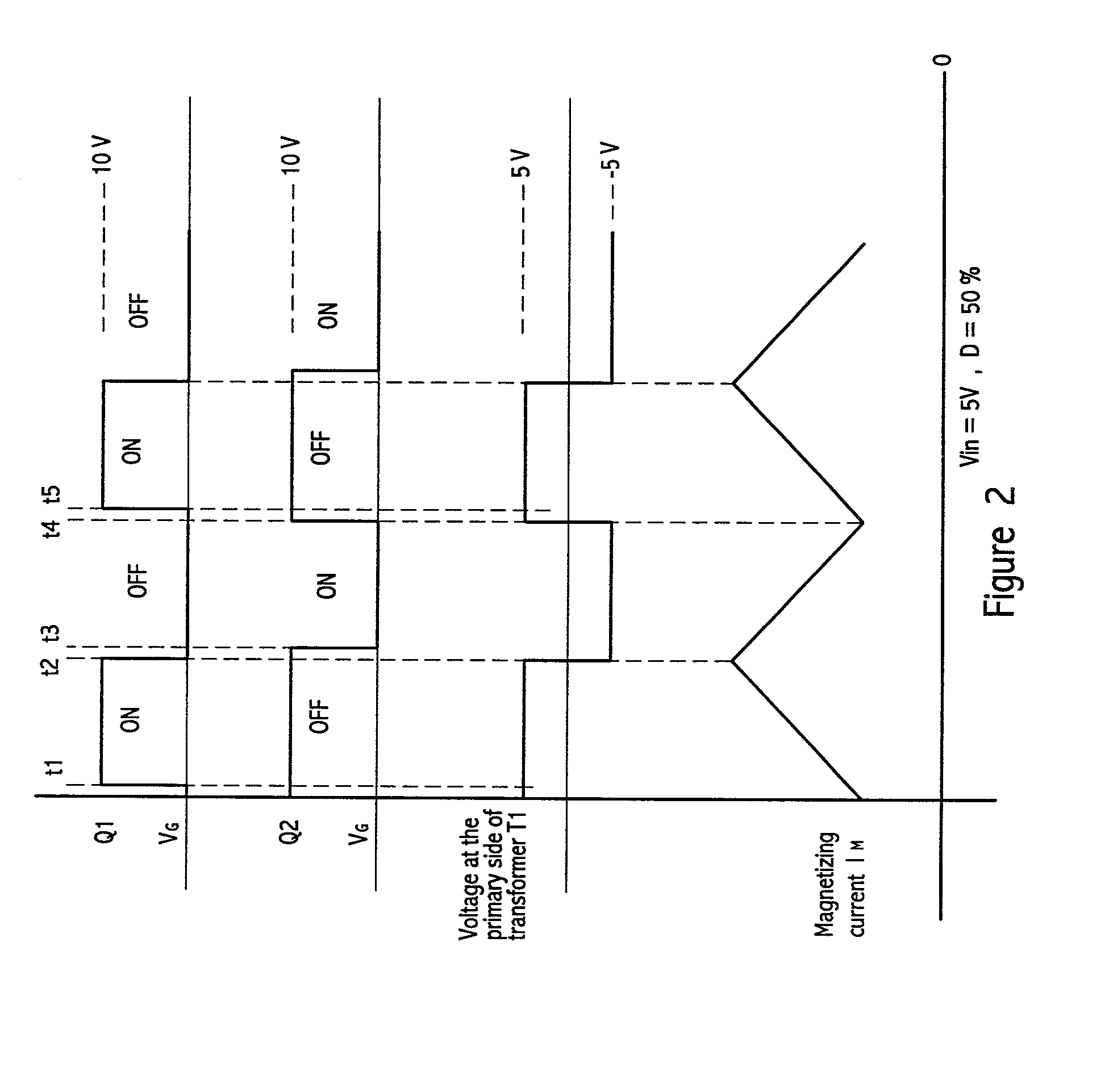
[0020] FIG. 1 shows the combination of an inverter and a discharge lamp of the preferred embodiment according to the invention. An inverter 100 and a lamp Lp constitute a lamp ignition system. The inverter 100 according to the first preferred embodiment of the invention comprises a transformer T1, a switch transistor Q1, a switch transistor Q2, and a reset capacitor C1. One of the source / drain of the switch transistor Q1 is electrically coupled to the primary side of the transformer T1 at node A while the other of the source / drain thereof is electrically coupled to the reset capacitor C1 at node B. One of the source / drain of the switch transistor Q2 is electrically coupled to the primary side of the transformer T1 at node A while the other of the source / drain thereof is electrically coupled to the reset capacitor C1 at node E. The discharge lamp Lp is electrically coupled to the secondary side of the transformer T1. A DC power source outputs DC voltage Vin to the inverter 100. In th...


PUM


Abstract

An inverter for igniting a discharge lamp comprises a transformer, a first switch transistor, a second switch transistor, a first snubber capacitor, a second snubber capacitor, a reset capacitor, and a control circuit. One of the source / drain of the first switch transistor is electrically coupled to the primary side of the transformer. One of the source / drain of the second switch transistor is electrically coupled to the primary side of the transformer. The first snubber capacitor is electrically coupled between the source and the drain of the first switch transistor. The second snubber capacitor is electrically coupled between the source and the drain of the second switch transistor. The reset capacitor is electrically coupled between the other of the source / drain of the first switch transistor and the other of the source / drain of the second switch transistor. The control circuit controls the first switch transistor and the second switch transistor so that the two transistors will not conduct at the same time.

Description

BACKGROUND OF THE INVENTION[0001] 1. Field of the Invention[0002] The present invention relates to an inverter in a lamp ignition device, particularly to a mono-stage high-efficiency inverter for the backlight module of a liquid crystal display (LCD).[0003] 2. Description of the Related Art[0004] Discharge lamps, such as cold cathode fluorescent lamps (CCFLs), are usually used as the backlight source of LCD panels Such a lamp has terminal voltage characteristics that vary with the immediate status and the frequency of the stimulus (AC signal) applied to the lamp. The CCFL will not conduct current until it is struck or ignited. When the lamp conducts current, the applied terminal voltage is less than the strike voltage. For example, the terminal voltage must be greater than or equal to 1500 V to strike the lamp. Once an electrical arc is strike in the CCFL, the terminal voltage falls to a lower run voltage, which is approximately one third of the strike voltage, and the current input...

Claims


Application Information

Patent Timeline
Patent Type & Authority Applications(United States)
IPC IPC(8): H02M7/48H05B41/24H05B41/282H05B41/392
CPCH05B41/2824
Inventor CHU, YI-SHANHSU, CHENG-CHIA
Owner HON HAI PRECISION IND CO LTD
Why Eureka
Try Eureka