
Acoustic wave touch actuated switch

Inactive Publication Date: 2002-09-12
TEXZEC
View PDF11 Cites 23 Cited by
  • Summary
  • Abstract
  • Description
  • Claims
  • Application Information

AI Technical Summary

Benefits of technology

[0007] In accordance with the present invention, the disadvantages of prior switches as discussed above have been overcome. In accordance with the present invention, acoustic wave energy is substantially trapped in an acoustic cavity so as to provide an acoustic wave switch with a high Q. Because the Q of the switch is high, a touch can be detected with extremely simple circuitry.
[0008] More particularly, the acoustic wave switch of the present invention includes a substrate with an acoustic wave cavity formed therein such that the mass per unit surface area of the acoustic cavity is greater than the mass per unit surface area of the substrate adjacent the cavity. An acoustic wave transducer is mounted on the acoustic cavity to generate an acoustic wave that is substantially trapped in the acoustic cavity. Even a light touch on a touch surface of the cavity produces a change in the impedance of the transducer that is easily detectable by a simple, low cost circuit.
[0009] In one embodiment of the switch, a thin mesa or plateau is formed on the substrate to define the acoustic cavity. Specifically, the acoustic cavity is formed of the mesa and the portion of the substrate below the mesa. The mesa may be formed on the touch surface side of the substrate or on a side of the substrate opposite the touch surface. The mesa can be an integral part of the substrate by mechanically or chemically machining the substrate. Alternatively, the mesa can be formed by adhering material to the substrate in a localized area to define the acoustic cavity. In the latter embodiment, the material forming the mesa may be the same as or a different material than the material forming the substrate. The substrate may be formed of metal, plastic, glass or ceramics, etc., capable of supporting a resonant acoustic wave. Moreover, the switch can use a wall of a housing or device enclosure as the substrate so that at least a portion of the switch, i.e. the acoustic cavity is an integral part of the housing wall. As such, no holes have to be formed in the housing or enclosure to accommodate the switch, eliminating sealing problems and providing a switch which is extremely rugged.
[0011] The acoustic wave switch of the present invention is low-cost, rugged, explosion proof, operates with simple, low-powered electronics and continues to function in the presence of ionizing environments, liquids and other contaminants. These and other objects, advantages and novel features of the present invention, as well as details of an illustrated embodiment thereof, will be more fully understood from the following description and drawings.

Problems solved by technology

Further, the enclosure through which touch is sensed cannot be made of an electrically conducting material, so that metals and the like cannot be used.
This type of switch is expensive compared to a standard membrane switch and shares the disadvantages of membrane switches in that holes in the housing or enclosure are required to accommodate the switch.
Further, the metal overlay is necessarily thin, so that the piezoelectric element is relatively unprotected against blows to the overlay.
This type of switch is relatively expensive and again requires openings in the housing or enclosure in which the switch is to be mounted.
As such, the ratio of the stored energy to lost or dissipated energy over a complete cycle, referred to as the Q of the switch, is inherently low and an extremely complex touch detection circuit is required to discriminate between a touch and the absence of a touch.
Moreover, the use of compressional waves in this switch is undesirable due to their sensitivity to liquids and other contaminants which can render the switch inoperable.
These systems are undesirable, however, because surface acoustic waves are sensitive to liquids, sealing compounds and other contaminants that can render the panel inoperable and difficult to seal effectively.
Although this touch position sensor is insensitive to liquids and contaminants, touch position sensors that use reflective gratings or arrays and the associated touch detection circuitry are, in general, too expensive to use for an individual switch or for a small number of switches on a panel.

Method used


Image

  • Acoustic wave touch actuated switch
  • Acoustic wave touch actuated switch
  • Acoustic wave touch actuated switch

Examples


Embodiment Construction

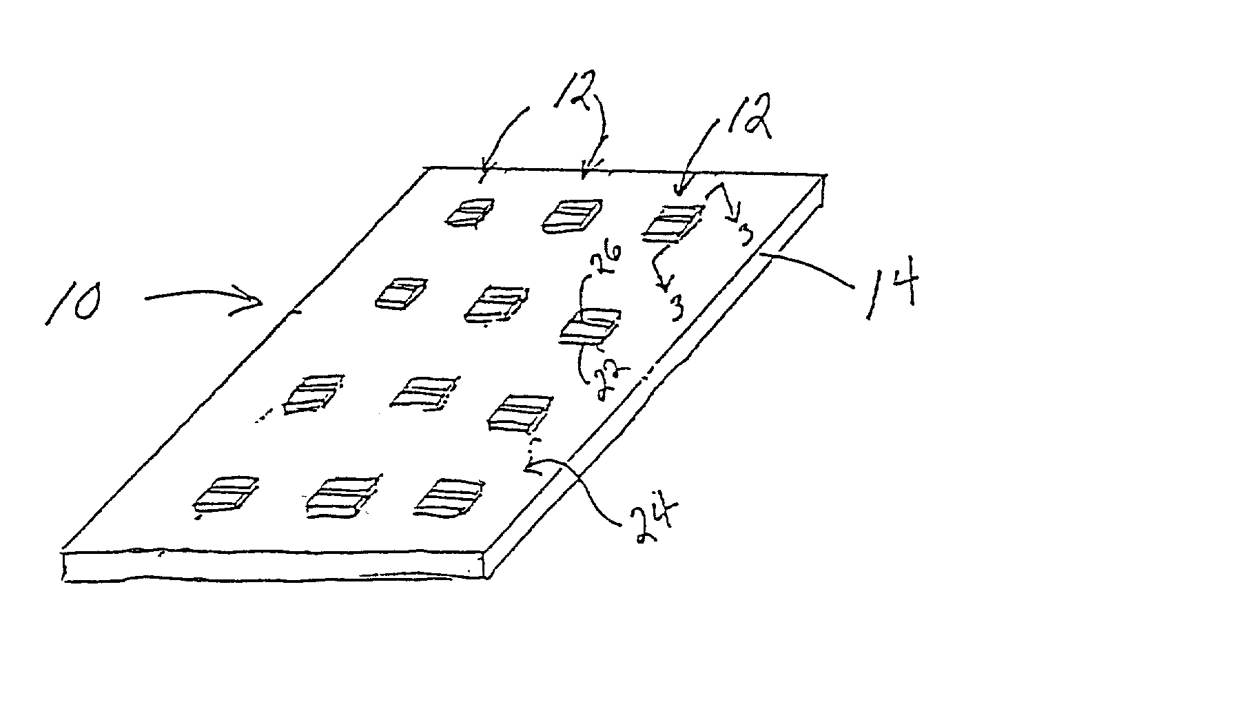
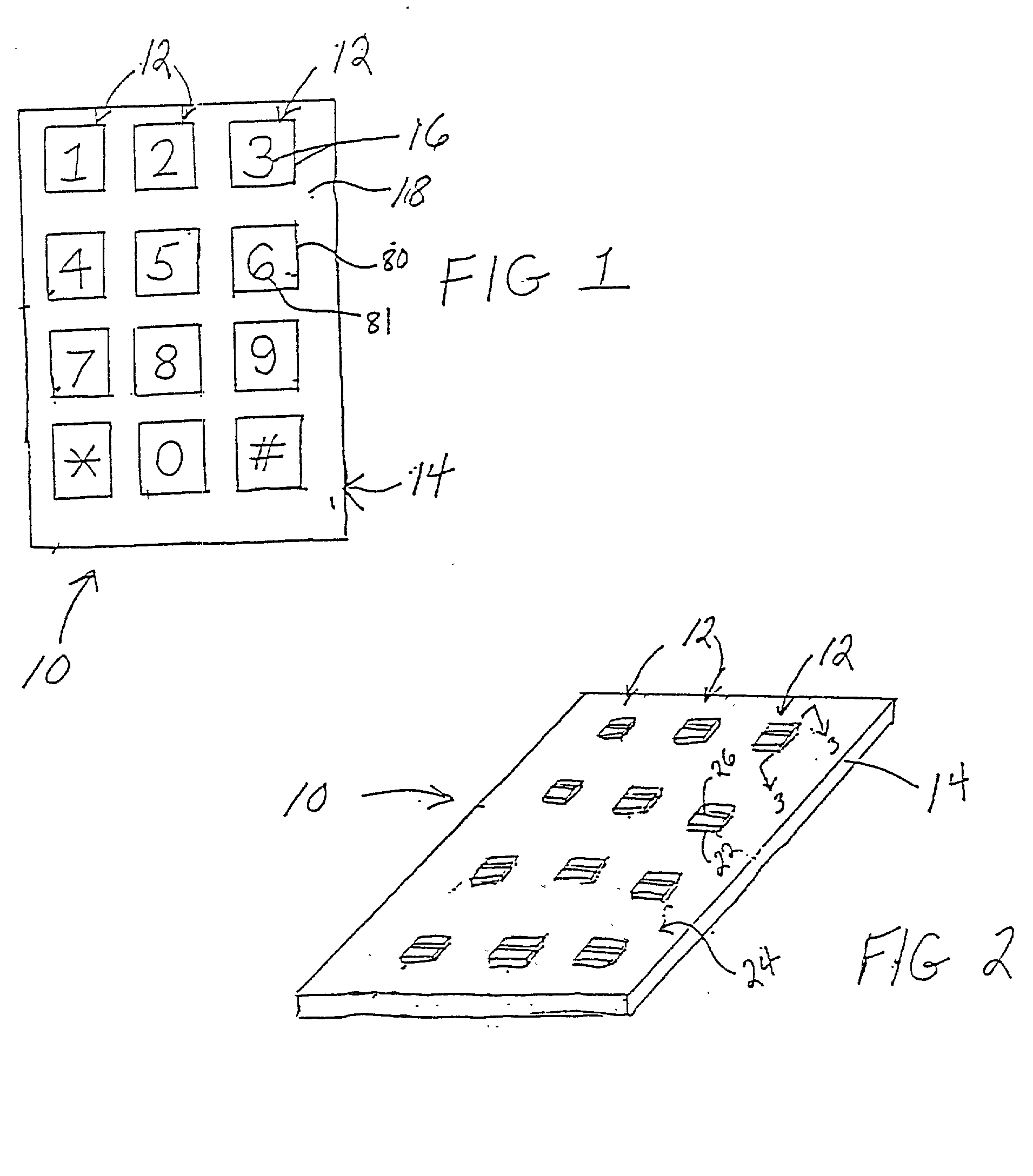
[0033] A touch panel 10 as shown in FIGS. 1 and 2 has a number of acoustic wave switches 12 in accordance with the present invention formed in the substrate 14 of the touch panel. Each acoustic wave switch 12 has respective indicia 16 formed on a top surface 18 of the panel. The indicia 16 identifies the position of a switch 12 and a switch actuation touch surface which are centrally located in the indicia 16.The indicia 16 can be formed in a number of different ways as described in detail below.

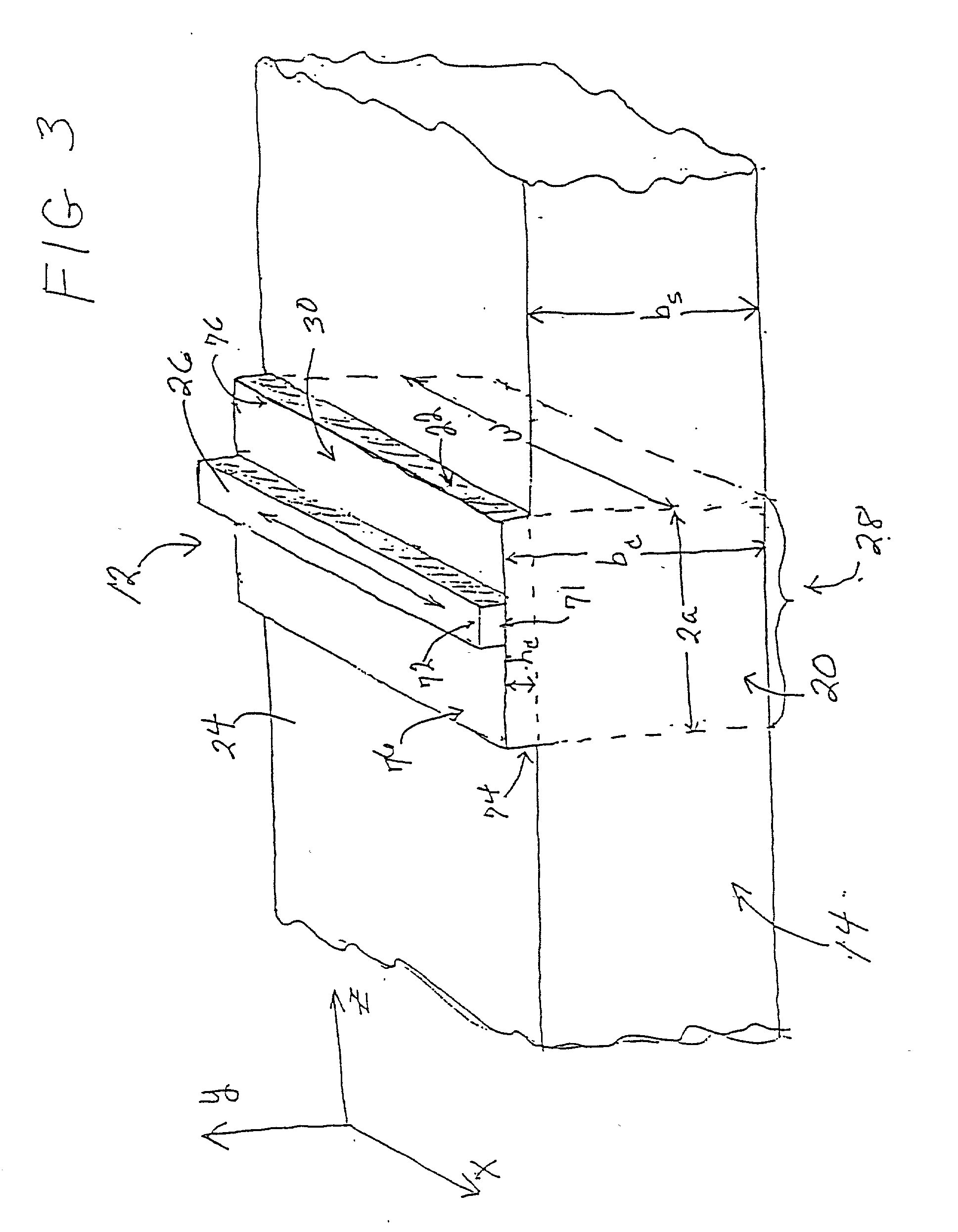
[0034] As shown in FIG. 2 and in more detail in FIG. 3, each acoustic wave switch 12 has an associated acoustic wave cavity 20 that extends through the thickness b.sub.s of the substrate 14. The acoustic wave cavity 20 is formed in the substrate 14 such that the mass per unit surface area of the acoustic wave cavity 20 is greater than the mass per unit surface area of the substrate adjacent the cavity. In one embodiment, the mass per unit area of the substrate in the switch region is increas...


PUM


Abstract

An acoustic wave switch includes a substrate with an acoustic wave cavity formed therein such that the mass per unit area of the acoustic cavity is greater than the mass per unit area of the substrate adjacent the cavity. A transducer is mounted on the acoustic cavity for generating an acoustic wave that is substantially trapped in the cavity. A touch on the touch surface of the acoustic wave cavity absorbs acoustic wave energy and produces a detectable change in the impedance of the transducer. The acoustic wave switch has a high Q so as to enable a touch to be detected by extremely simple, low-cost circuitry. The acoustic wave switch of the present invention is rugged, explosion proof, operates in the presence of liquids and other contaminants, has a low power consumption and can be incorporated and integrally formed in a wall of a housing for a device.

Description

CROSS-REFERENCE TO RELATED APPLICATIONS[0001] This application is a continuation-in-part of U.S. application Ser. No. 09 / 766,000 filed Jan. 18, 2001 entitled ACOUSTIC WAVE TOUCH ACTUATED SWITCH.STATEMENT REGARDING FEDERALLY SPONSORED RESEARCH OR DEVELOPMENT[0002] N / AFIELD OF INVENTION[0003] The present invention relates to an acoustic wave touch actuated switch and more particularly to such a switch having an acoustic cavity that substantially traps acoustic wave energy so as to provide a high Q switch.BACKGROUND OF THE INVENTION[0004] There is a substantial need for finger touch actuated switches that are rugged and explosion proof, operate in the presence of liquids, have low power consumption, withstand aggressive sterilization procedures and are inexpensive. Known switches that attempt to meet these needs but fail include the following. A Qprox switch made by Quantum Research Group senses the presence of touch through a charge transfer effect. This switch is sensitive to conduct...

Claims


Application Information

Patent Timeline
IPC IPC(8): G06F3/033H03K17/96
CPCG06F3/0436H01H2239/054H03K17/96H03K17/964H03K2217/96011
Inventor KNOWLES, TERENCE J.BREMIGAN, CHARLES F. IIIKALMUS, CHRIS
Owner TEXZEC
Learn More