High linearity circuits and methods regarding same

a high linearity, circuit technology, applied in the field of electric circuits, can solve the problems of low linearity, low linearity, and limited system accuracy, and achieve the effects of improving the linearity of cmos circuits, low noise, and high linearity

Inactive Publication Date: 2002-09-12
RGT UNIV OF MINNESOTA
View PDF5 Cites 65 Cited by
  • Summary
  • Abstract
  • Description
  • Claims
  • Application Information

AI Technical Summary

Benefits of technology

0019] The techniques described above have been proposed to improve the linearity of CMOS circuits. However, for example, low noise amplifiers used in wireless communication systems need to have low noise, high linearity, and sufficient gain. Although CMOS is the technology of choice in terms of digital integration, it is seldom preferred for high performance circuits such as low noise amplifiers due to its limited ability in handling interference and because it generally is not suitable for the high performance requirements of various communication systems, such as first tier wireless systems, e.g., CDMA, and W-CDMA.

Problems solved by technology

Circuit nonlinearity causes many problems.
For example, circuit nonlinearity limits a system's spurious-free dynamic range (SFDR).
As a result, a system's accuracy is limited.
The design of communication systems, e.g., the design of a high performance receiver, is made challenging by various design constraints.
First, high performance is required for many applications.
Second, for some applications such as in a cellular communication system, power consumption is an important consideration because of the portable nature of the receiver.
However, all active devices experience some amount of nonlinearity which is quantified by the coefficients a.sub.2 and a.sub.3.
Nonlinearity within the active devices causes intermodulation of spurious signals, resulting in products which may fall into the signal band.
However, third-order nonlinearity is more problematic.
Thus, near band spurious signals (which are difficult to filter) can produce third-order intermodulation products that fall in-band, causing degradation in the received signal.
In summary, nonlinearity in a communication system causes many problems, including, for example, cross-modulation, inter-modulation, gain compression, and desensitization.
However, conventional CMOS designs are generally not suitable for high performance requirements, e.g., high linearity systems, for many communications systems, e.g., CDMA, W-CDMA, and OFDM wireless systems.
Such designs generally are not easily incorporated with other digital circuits on the same chip.
As such, product cost increases significantly due to the use of the multiple technologies.
In addition, power considerations become problematic.
However, such transconductors do not operate at sufficiently high frequencies, e.g., in gigahertz frequencies.
Further, such transconductors do not meet the high linearity requirements of modern communication systems.
However, for example, low noise amplifiers used in wireless communication systems need to have low noise, high linearity, and sufficient gain.
Although CMOS is the technology of choice in terms of digital integration, it is seldom preferred for high performance circuits such as low noise amplifiers due to its limited ability in handling interference and because it generally is not suitable for the high performance requirements of various communication systems, such as first tier wireless systems, e.g., CDMA, and W-CDMA.

Method used


Image

  • High linearity circuits and methods regarding same
  • High linearity circuits and methods regarding same
  • High linearity circuits and methods regarding same

Examples


Embodiment Construction

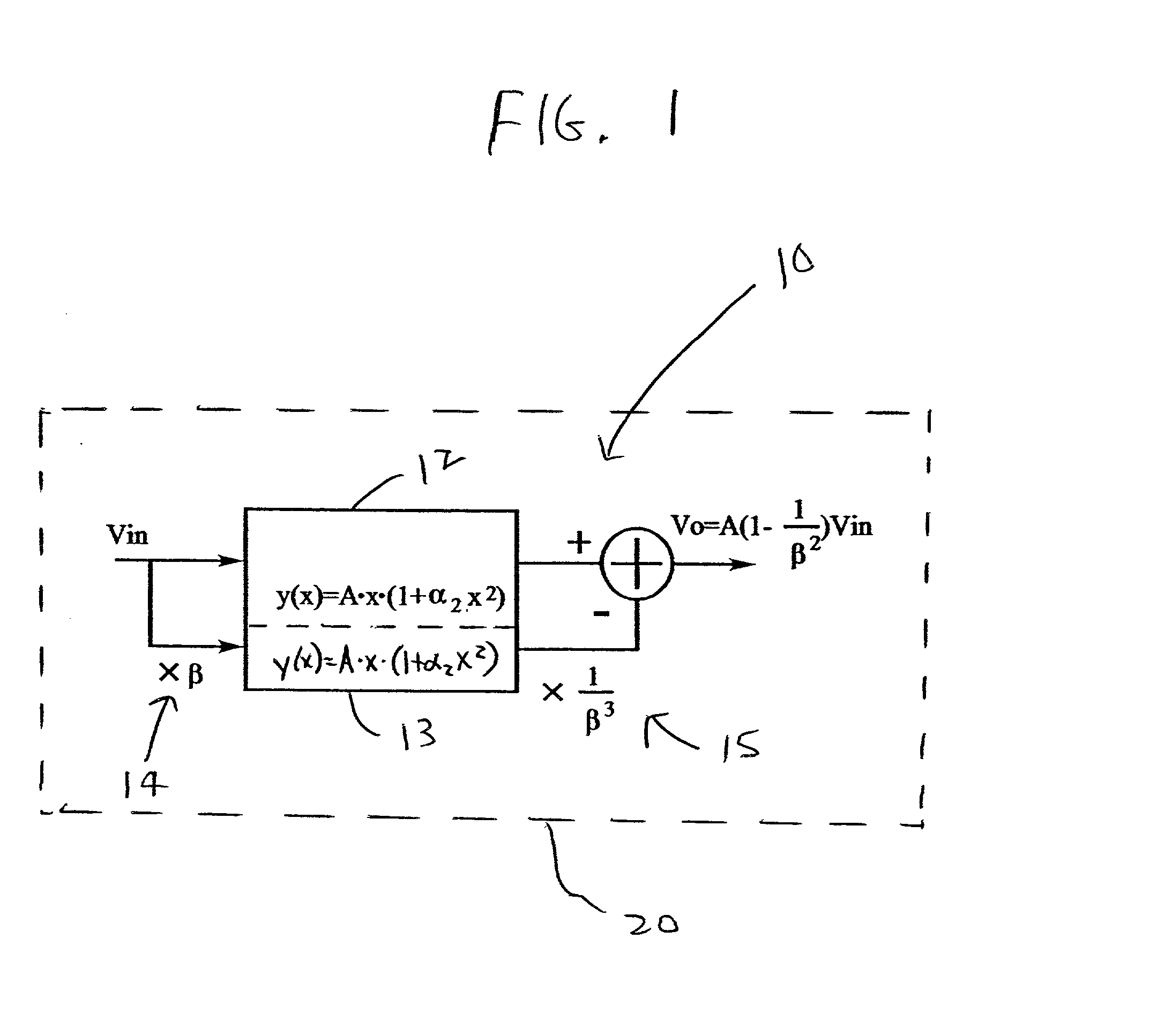
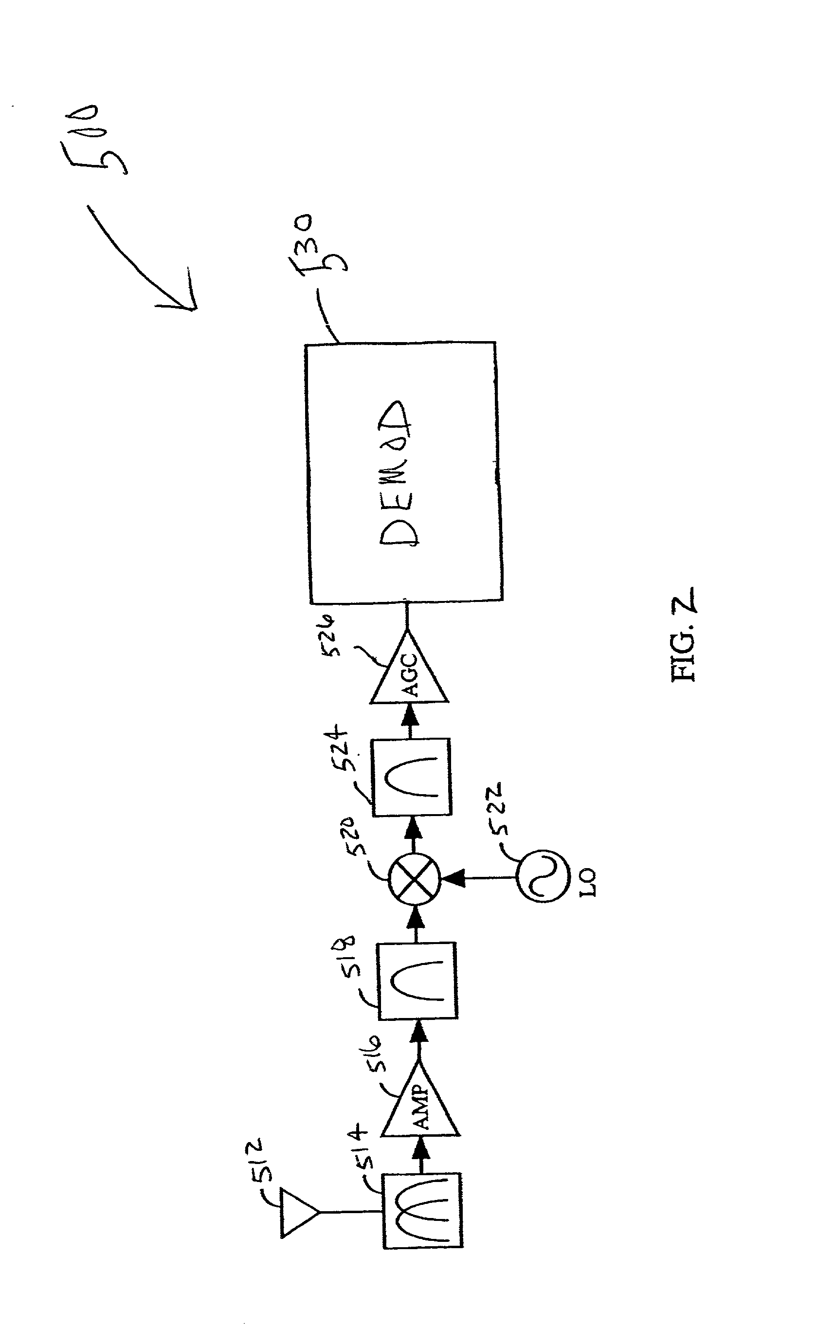
[0045] The present invention shall be generally described with reference to at least FIG. 1. Thereafter, various embodiments of the present invention and more details regarding such embodiments shall be provided and described with reference to FIGS. 2-12.

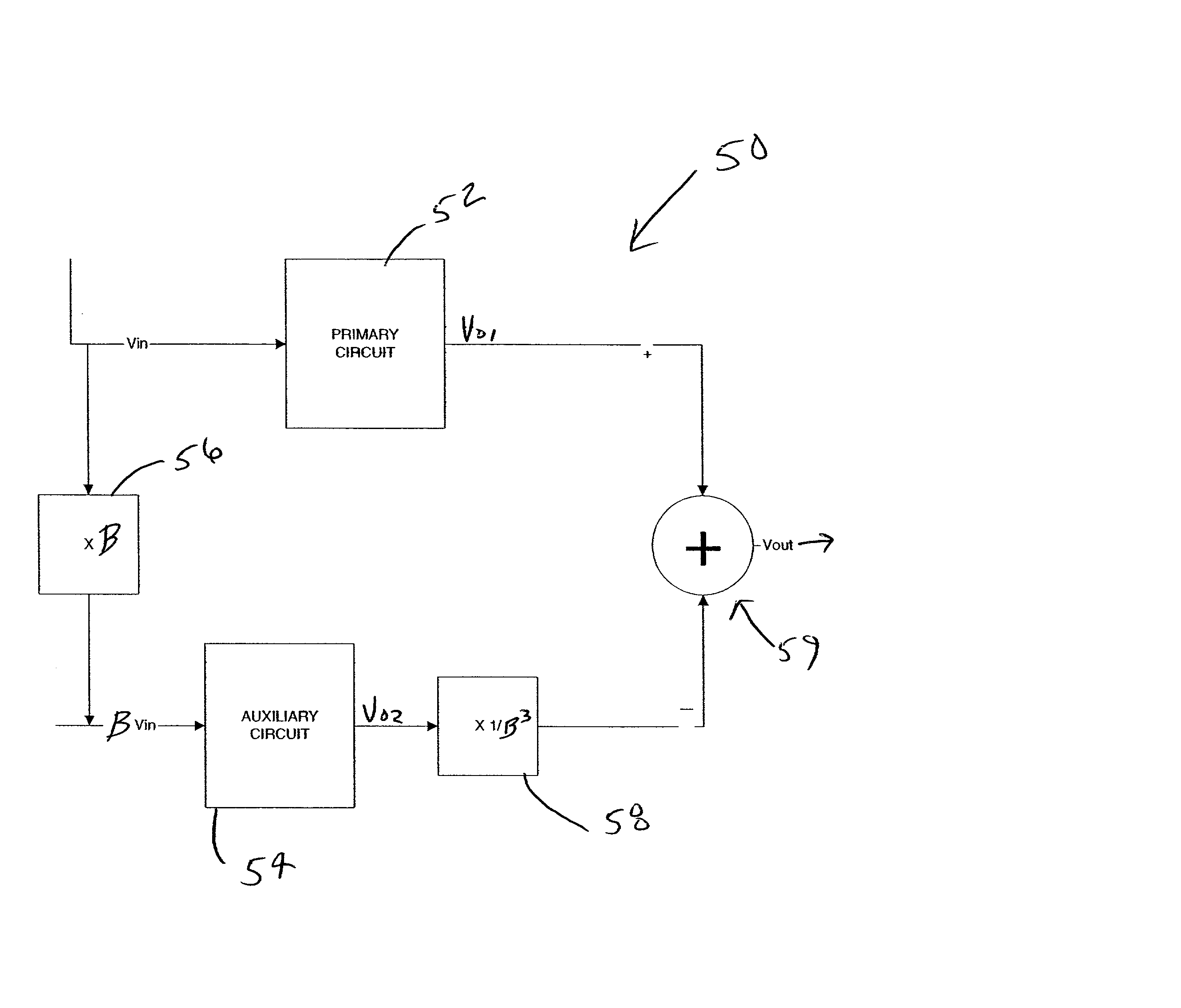
[0046] FIG. 1 shows generally a circuit apparatus 10 having high linearity according to the present invention used in a system 20. The circuit apparatus 10 employs a technique to provide high linearity.

[0047] Generally, the basic technique relies on canceling at least a portion, and preferably, substantially all of, the most significant harmonic from the output of a primary circuit 12 having an input V.sub.in provided thereto, e.g., the most significant harmonic typically being the 3.sup.rd harmonic. The nonlinear primary circuit 12 can be modeled as an imperfect linear, time-invariant (LTI) system with 3.sup.rd harmonic, as follows:

y(x)=A.multidot.x.multidot.(1+a.sub.2.multidot.x.sup.2)

[0048] Generally, an auxiliary input signal wh...


PUM


Abstract

Circuits and methods that improve linearity with use of cancellation of at least a portion, and preferably, substantially all of, at least one significant harmonic from the output of a primary circuit, e.g., the 3.sup.rd harmonic, using the output of a substantially functionally identical auxiliary circuit.

Description

CROSS-REFERENCE TO RELATED APPLICATIONS[0001] This application claims the benefit of U.S. Provisional Application No. 60 / 264,105, entitled "HIGH LINEARITY CIRCUITS AND METHOD REGARDING SAME," filed Jan. 25, 2001, wherein such document is incorporated herein by reference.TECHNICAL FIELD OF THE INVENTION[0002] The present invention relates generally to electrical circuits. More particularly, the present invention pertains to high linearity circuits, such as, for example, those employed in analog circuits, e.g., low noise amplifiers.BACKGROUND OF THE INVENTION[0003] High linearity circuits are required in a large number of systems, such as receivers and transmitters of communication systems, and analog-to-digital (A / D) conversion systems. Circuit nonlinearity causes many problems. For example, circuit nonlinearity limits a system's spurious-free dynamic range (SFDR). As a result, a system's accuracy is limited. A highly linear design can not only improve a circuit's SFDR, but can also ...

Claims


Application Information

Patent Timeline
Patent Type & Authority Applications(United States)
IPC IPC(8): H03F1/32H03F3/193H03F3/45
CPCH03F1/3211H03F3/193H03F3/45183H03F2200/372H03F2200/453
Inventor DING, YONGWANGHARJANI, RAMESH
Owner RGT UNIV OF MINNESOTA
Why Eureka
Try Eureka