Cannula assembly

a cannula and assembly technology, applied in the direction of liquid degasification, catheters, separation processes, etc., can solve the problems of obstructing the surgeon's view of the operative site, exposing the surgeon and the surgeon's staff to a health risk, and entering the abdominal cavity, etc., to achieve the effect of reducing odor, facilitating addition, and facilitating surgical procedures

Inactive Publication Date: 2002-09-12
PALL CORP
View PDF5 Cites 89 Cited by
  • Summary
  • Abstract
  • Description
  • Claims
  • Application Information

AI Technical Summary

Benefits of technology

0012] In preferred embodiments of de-sufflation applications, the gas filter removes laparoscopic smoke and reduces odor as the gas passes through the cannula assembly to the exterior of the housing.
0013] Embodiments of the cannula and cannula assembly are suitable for use at any desirable constant or variable gas flow rate, and de-sufflation can be carried out without attaching a vacuum system to the assembly. Preferably, the cannula assembly can be easily added to any suitable system (e.g., a system for use in laparoscopic surgery). In an embodiment, the assembly (that can be part of a system) allows one-handed gas flow adjustment.
0014] Embodiments of the invention are particularly for use in surgical environments, especially for use in laparoscopic surgery, as they can allow the surgical procedure to be completed more quickly and / or cost efficiently, e.g., by reducing the amount of valuable surgeon-, nurse-, technician- and / or operating room-time needed for the procedure. Time savings are particularly advantageous, since, for example, as of 1999, studies have estimated the value of time in the operating room during laparoscopic surgery as in the range of from $20 per minute to $120 per minute, or more.

Problems solved by technology

However, this cutting often produces "smoke" (e.g., vapor and / or mist) that can cloud or obstruct the surgeon's view of the operative site.
Smoke can contain toxic, odiferous, and otherwise undesirable material that, if released into the environment of the operating room, could expose the surgeon and the surgeon's staff to a health risk.
Additionally, the gas to be introduced into the abdominal cavity can include undesirable material such as particulate and / or microbial contaminants.
However, these device arrangements (i.e., an external filter attached to a cannula fitting) have suffered from a number of drawbacks.
For example, some of these device arrangements are bulky and / or heavy, and can interfere with the ability to move in and around the surgical site.
The combined weight of the cannula and filter can put strain on the incision and / or cause leakage of gas.
The filters may become plugged, fail to remove sufficient undesirable material and / or may require a labor intensive effort (possibly requiring numerous steps) to attach and operate them.

Method used


Image

  • Cannula assembly
  • Cannula assembly
  • Cannula assembly

Examples


Embodiment Construction

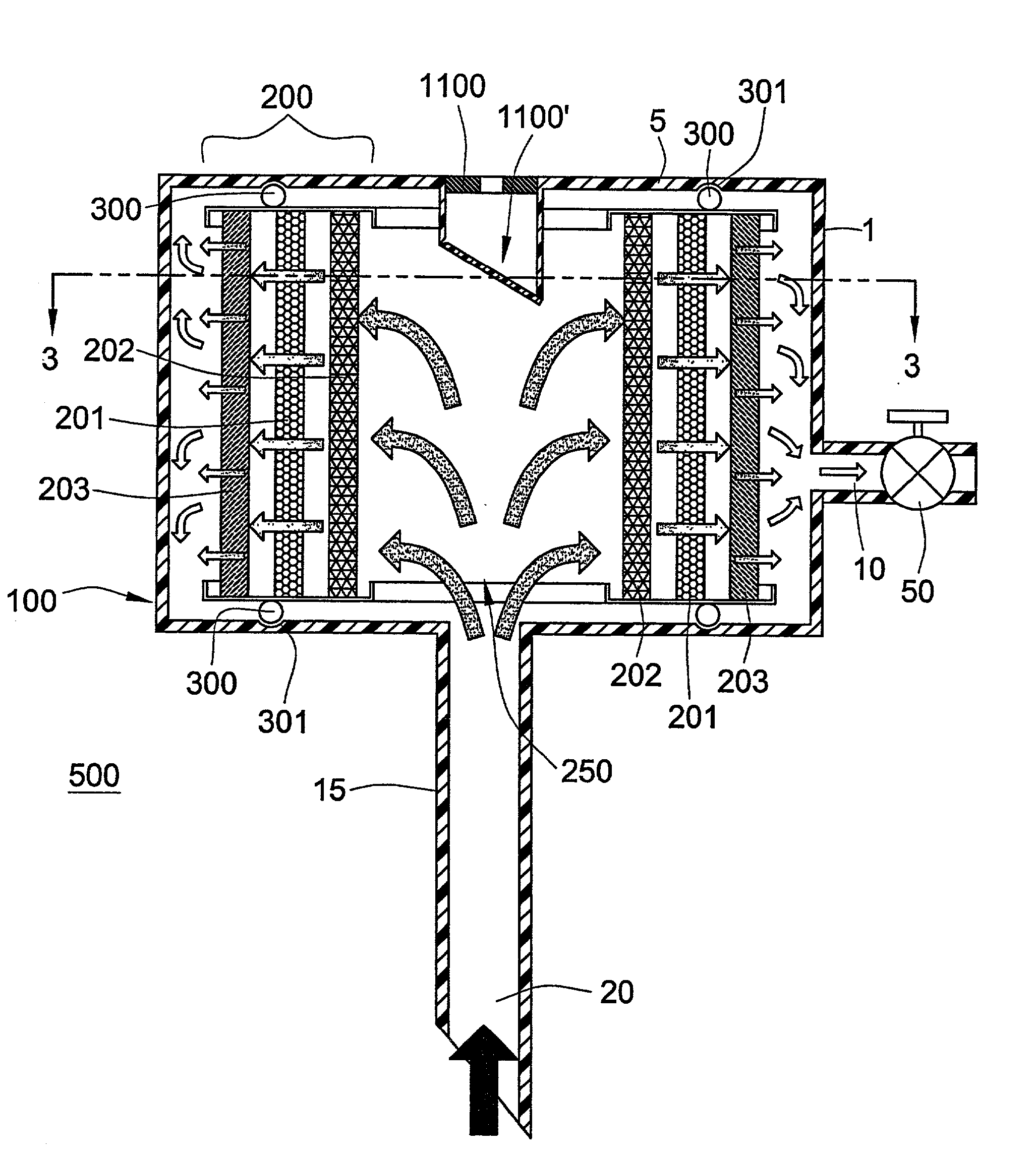
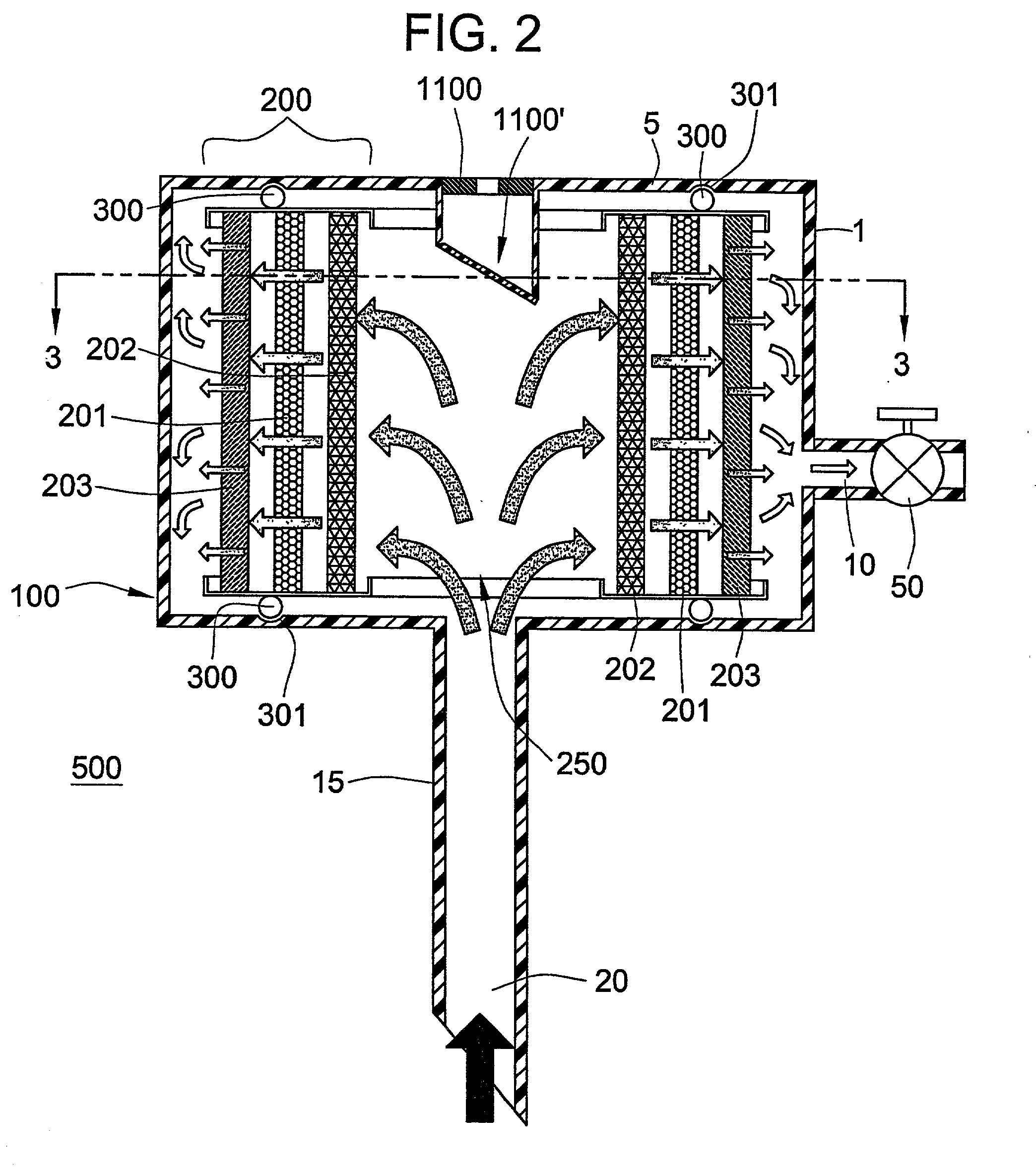
[0038] A cannula assembly according an embodiment of the invention comprises a housing having at least a first port and a second port, and defining a fluid flow path between the two ports, and a gas filter disposed in the housing, across the fluid flow path.

[0039] In accordance with an embodiment of the invention, a cannula assembly is provided comprising a housing having at least a first port and a second port, the housing comprising a sleeve wherein the sleeve comprises the second port, wherein said housing defines a fluid flow path between the first port and the second port, and a gas filter disposed in the housing, across the fluid flow path, wherein said gas filter comprises at least one gas filter element comprising at least one porous medium.

[0040] A cannula assembly according to another embodiment of the invention comprises a housing having at least a first port and a cannula sleeve, the cannula sleeve comprising a second port, wherein said housing defines a fluid flow path ...


PUM

PropertyMeasurementUnit
filtration areaaaaaaaaaaa
diameteraaaaaaaaaa

Abstract

Cannulas, as well as cannula assemblies including gas filters, are disclosed.

Description

[0001] This application claims the benefit of U.S. provisional patent application No. 60 / 231,299, filed Sep. 8, 2000, which is incorporated by reference.TECHNICAL FIELD[0002] This invention relates to cannulas and cannula assemblies for use with surgical instruments and / or for use in filtering gas.BACKGROUND OF THE INVENTION[0003] During some medical procedures, e.g., laparoscopic and endoscopic surgery, a suitable gas is introduced into the abdominal cavity to inflate the abdomen, and this introduction of gas is commonly referred to as insufflation. The inflation of the abdomen separates the interior organs and provides an enlarged cavity within which to perform the surgery. Typically, one or more trocars (slidably disposed in a cannula or cannula sleeve) are used to puncture the abdomen, the trocar is withdrawn, and insufflation gas is passed through at least one of the cannula(s) to inflate the abdomen. One or more instruments involved in the procedure, e.g., a laparoscope, scalp...

Claims


Application Information

Patent Timeline
Patent Type & Authority Applications(United States)
IPC IPC(8): A61M5/165A61B17/34A61B18/00B01D19/00
CPCA61B17/3421A61B17/3474A61B2017/3437A61B2218/008B01D19/0031
Inventor BOOTH, CHARLES S.MCDONOUGH, DAVID
Owner PALL CORP
Why Eureka
Try Eureka