Cylinder injection type internal combustion engine
a technology of internal combustion engine and injection cylinder, which is applied in the direction of machines/engines, automatic control of ignition, electrical control, etc., can solve the problems of higher fuel consumption and higher fuel consumption, and achieve the effect of improving the efficiency of raising the temperatur
- Summary
- Abstract
- Description
- Claims
- Application Information
AI Technical Summary
Benefits of technology
Problems solved by technology
Method used
Image
Examples
first embodiment
[0057] First Embodiment
[0058] The temperature raising control for the former case will be discussed first.
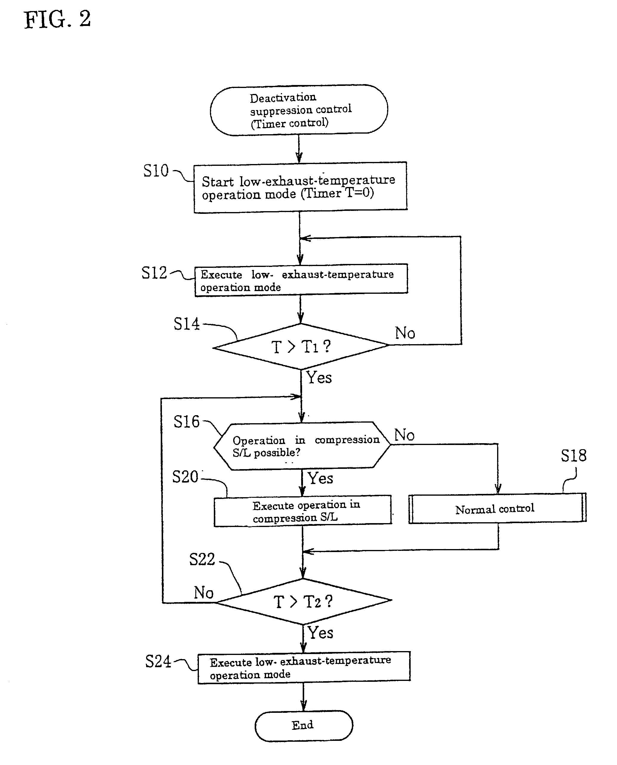
[0059] FIG. 2 is a flowchart illustrating a control routine for deactivation suppression control to prevent the temperature of the exhaust-gas purifying catalyst device 30 from falling below a predetermined temperature (e.g., the activation temperature), particularly, a control routine using a timer control. FIG. 3 presents a time chart of the deactivation suppression control. The first embodiment will now be explained referring to FIGS. 2 and 3.
[0060] First, in step S10, if it is determined, based on the aforementioned fuel injection mode map, that the operation mode is, for example, both the compression L mode and the idling mode where the engine speed Ne becomes low, i.e., the determined operation mode is the low-exhaust-temperature operation mode, a timer T used in this routine is reset to "0" and is made to start counting (see (a), (b), (c), and (d) in FIG. 3). Then, the lo...
second embodiment
[0092] Second Embodiment
[0093] The following describes the second preferred embodiment where the deactivation suppression control is carried out using an exhaust-temperature sensor control instead of the timer control employed in the first preferred embodiment.
[0094] FIG. 8 presents a flowchart illustrating a control routine for the deactivation suppression control based on an exhaust-temperature sensor control in the case where the exhaust-gas purifying catalyst device 30 is cooled down while the engine 1 is running. The following description will be given along the flowchart in FIG. 8 while also referring to the time chart in FIG. 3.
[0095] In the first step S30, it is determined if the execution of the operation in a low-exhaust-temperature operation mode has lowered the exhaust temperature Tex, detected by the exhaust-temperature sensor 32, to or below the aforementioned predetermined value (deactivation temperature) T.sub.ex0 (see (b) in FIG. 3). That is, while it is determined ...
third embodiment
[0104] Third Embodiment
[0105] The following discusses temperature raising control for the exhaust-gas purifying catalyst device 30 when the engine 1 is cold-started.
[0106] FIG. 9 presents a flowchart illustrating a control routine for the case of executing an operation in the compression S / L mode by an open-loop control (O / L control) under a timer control in the temperature raising control when the engine 1 is cold-started, i.e., in a cold-start temperature increase control to raise the temperature of the exhaust-gas purifying catalyst device 30 to a predetermined activation temperature from the low-temperature state. FIG. 10 presents a time chart showing the control contents of the cold-start temperature increase control. The third preferred embodiment will now be discussed with reference to the flowchart in FIG. 9 and the time chart in FIG. 10.
[0107] First, in step S40, when it is determined that the start switch (start SW) or ignition key (not shown) has been turned on and the en...
PUM
 Abstract
Description
Claims
Application Information
 - R&D
- Intellectual Property
- Life Sciences
- Materials
- Tech Scout
- Unparalleled Data Quality
- Higher Quality Content
- 60% Fewer Hallucinations
Browse by: Latest US Patents, China's latest patents, Technical Efficacy Thesaurus, Application Domain, Technology Topic, Popular Technical Reports.
© 2025 PatSnap. All rights reserved.Legal|Privacy policy|Modern Slavery Act Transparency Statement|Sitemap|About US| Contact US: help@patsnap.com


