Torsional damper

a technology of torsional dampers and dampers, which is applied in the direction of heat treatment equipment, machines/engines, furnaces, etc., can solve the problems of increased number of parts, increased manufacturing costs, and increased manufacturing costs of torsional dampers including crank shafts, and achieves high assembly efficiency, high abrasion resistance, and high welding strength

Inactive Publication Date: 2002-09-19
FUKOKU CO LTD
View PDF0 Cites 16 Cited by
  • Summary
  • Abstract
  • Description
  • Claims
  • Application Information

AI Technical Summary

Benefits of technology

[0010] On the contrary, in the torsional damper shown in FIG. 7, since the hub 2 is welded to the boss 8, the fixing strength of the hub 2 becomes high. However, the collar 9 having a high abrasion resistance must be fitted to the outside of the boss 8, and therefore such an operation is required that the collar 9 which is another part different from the boss 8 is press-inserted into the boss 8. As a result, the number of parts thereof is increased, and further the manufacturing cost becomes high.
[0012] An object of the present invention is to provide a torsional damper having high assembly efficiency with respect to a crank shaft.
[0013] Another object of the present invention is to provide a torsional damper that can obtain weld strength desired without thermally treating the weld portion between a hub and a boss welded thereto.
[0014] Sill anther object of the present invention is to provide a torsional damper in which a portion with which a seal element makes contact has high abrasion resistance.

Problems solved by technology

By doing so, the manufacturing cost of the torsional damper including the crank shaft is increased.
As a result, the number of parts thereof is increased, and further the manufacturing cost becomes high.
Accordingly, in order to manufacture the torsional damper shown in FIG. 7, three steps, that is, a welding step, a tempering step of the weld portion, and an induction-hardening step of induction-hardening a portion with which the seal element makes contact, are required, so that there arises the problem that the manufacturing cost of the torsional damper becomes high.

Method used


Image

  • Torsional damper
  • Torsional damper
  • Torsional damper

Examples


Embodiment Construction

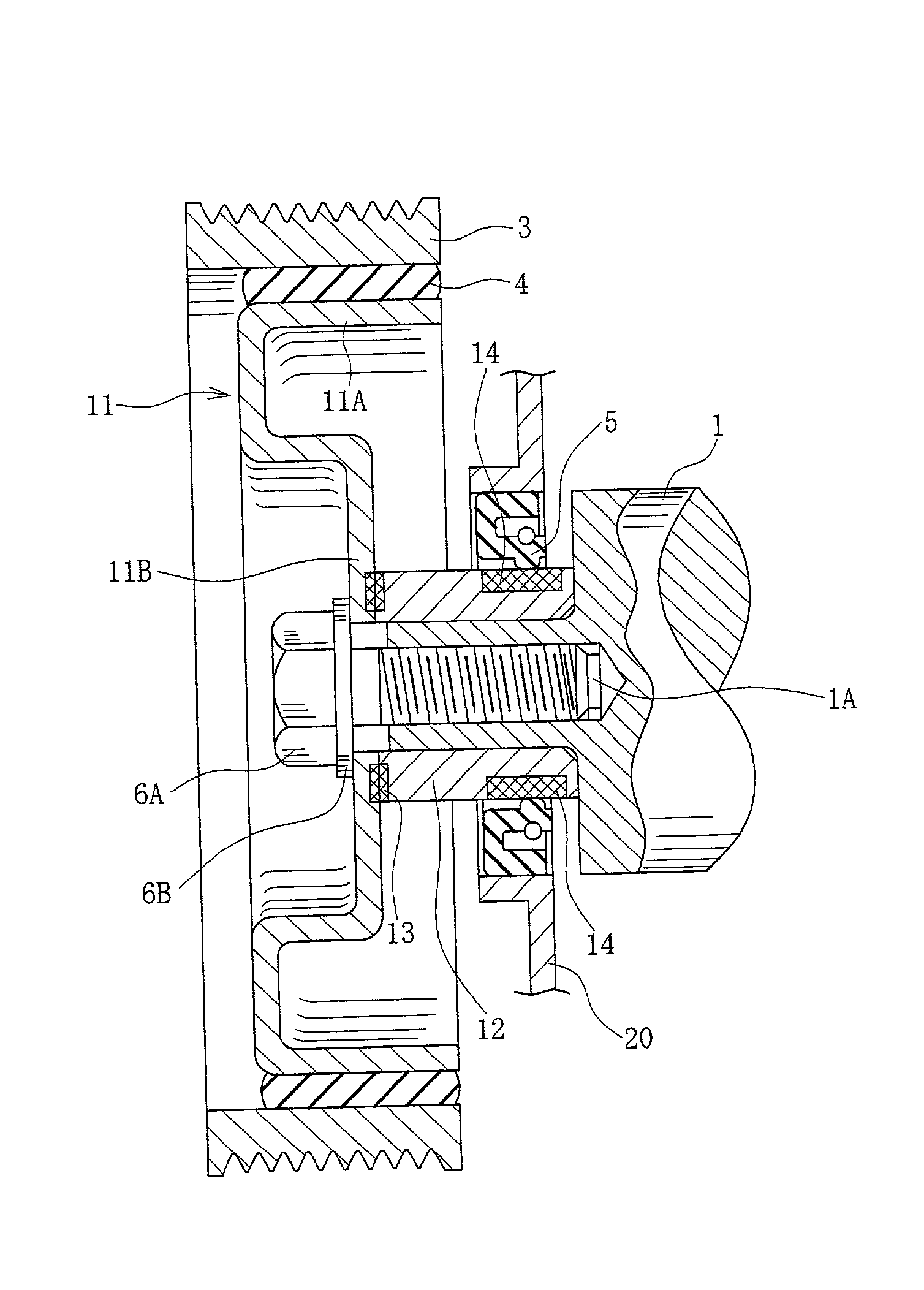
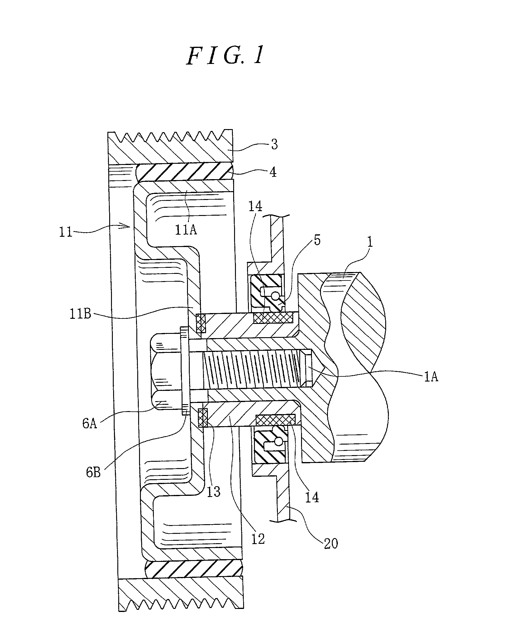
[0024] As shown in FIG. 1, a torsional damper according to the present invention has a hub 11 made of a sheet metal. The hub 11 is provided with a rim portion 11A substantially formed in a cylindrical shape, and a fixing portion 11B integrally formed with the rim portion 11A and extending in a diametrical direction. The hub 11 is made of a sheet metal and is formed by press-processing a plate-shaped material. A through hole is formed in the fixing portion 11B, and the hub 11 is firmly fixed to a crank shaft 1 via a washer 6B by a bolt 6A screw-connected to a female screw 1A which passes through the through hole and which is formed in the crank shaft 1. A material of the hub 11 is a carbon equivalent (Ceq) of 0.5% or less.

[0025] A cylindrical metal boss 12 is fitted to the outside of the crank shaft 1. An end surface of the boss 12 is firmly and integrally fixed to the fixing portion 11B of the hub 11 by welding. In FIG. 1, reference numeral 13 denotes a weld portion. A material of t...


PUM

PropertyMeasurementUnit
cylindrical massaaaaaaaaaa
abrasion resistanceaaaaaaaaaa
fixing strengthaaaaaaaaaa

Abstract

A torsional damper mounted to a crank shaft of an internal combustion engine has a hub provided with a rim portion and a fixing portion, and a boss welded to the rim portion. A mass body is arranged in an outer side of the rim portion via a cylindrical elastic body. A seal element of an oil seal mounted to an engine assembly makes contact with an outer circumferential surface of the boss. The hub 11 has a carbon equivalent of 0.5% or less, and a boss has a carbon equivalent of 0.5% or less and a carbon content of 0.2% or more. Induction hardening is applied to a portion of the boss with which the oil element makes contact.

Description

BACKGROUND OF THE INVENTION[0001] The present invention relates to a torsional damper mounted to a crank shaft of an internal combustion engine.[0002] A torsional damper is mounted to a crank shaft of an internal combustion engine in order to reduce a torsional vibration generated in the crank shaft. The torsional damper is generally mounted to a pulley portion with taking a mounting space into consideration.[0003] FIG. 5 is across-sectional view showing a conventional torsional damper. In FIG. 5, a hub 2 is fixed to a crank shaft 1 in an internal combustion engine. This hub 2 has a cylindrical rim portion 2A extending in an axial direction and a fixing portion 2B integrally formed therewith and extending in a diametrical direction, and is formed by press-processing a sheet material. A surface of the fixing portion 2B makes contact with an end surface of the crank shaft 1. The hub 2 is fixed to the crank shaft 1 via a washer 6B by a bolt 6A screw-connected to a female screw 1A forme...

Claims


Application Information

Patent Timeline
Patent Type & Authority Applications(United States)
IPC IPC(8): F02B77/00C21D9/40C22C38/00F16F15/12F16F15/126F16F15/16F16F15/30
CPCF16F15/1203F16F15/1207F16F15/126F16H55/36Y10T428/31696Y10T74/2131F16F15/16
Inventor WATANABE, HIDEAKIYOSHIDA, TAKASHI
Owner FUKOKU CO LTD
Why Eureka
Try Eureka