
Artificial sphincter

Inactive Publication Date: 2002-09-19
TOKIN CORP
View PDF0 Cites 14 Cited by
  • Summary
  • Abstract
  • Description
  • Claims
  • Application Information

AI Technical Summary

Benefits of technology

[0017] It is an object of the present invention to provide an artificial sphincter for which repeated shape changes are possible, and for which the quantity of shape change is sufficient so as to be used as a substitute for a natural sphincter.
[0018] It is another object of the present invention to provide an artificial sphincter that eliminates inconveniences of the aforementioned conventional examples, and for which electrical power supply is possible without passing a lead wire through the skin, thus avoiding risk of infection.

Problems solved by technology

With all pouches available on the market, the whole or part of the pouch must be replaced after defecation, and an unpleasant odor may leak out.
Due to such problems, there is a drawback that everyday social life becomes troublesome.
There is an inconvenience in that, every time defecation occurs, the cover must be removed and then reattached.
Moreover, there is also the possibility of excrement or gas leaking out from gaps between the cover and the opening.
However, the shape memory alloy (SMA) ring used here has locally large distortion and poor repetition characteristics, making it difficult to change the shape repeatedly.
Moreover, when a shape memory alloy element is embedded in a narrow region, namely an intestinal opening on the surface of the body, the intestine is subjected to a local force, and there is thus a risk of damage to this part of the body.
Moreover, the power source for heating is embedded between the skin and the muscularis, meaning that replacement when the small battery has been exhausted is troublesome.
In particular, the small battery and the push switch that constitute the power source for heating are connected to the shape memory alloy (SMA) ring via a lead wire, and so the choice of installment location is somewhat limited.
Furthermore, the lead wire must be a certain length, and there is a risk of infection along this part.
One could also envisage transmitting electrical power into the body from a power source outside the body via a lead wire, but then there would be a risk of infection from the electrode part passing through to the outside of the body.
Moreover, even in the case of a 2-way shape memory alloy, it is difficult to achieve a quantity of shape change from the state in which the ring is squashed flat such that the opening opens to a sufficient size for unimpeded defecation to be possible.

Method used


Image

  • Artificial sphincter
  • Artificial sphincter
  • Artificial sphincter

Examples


first embodiment

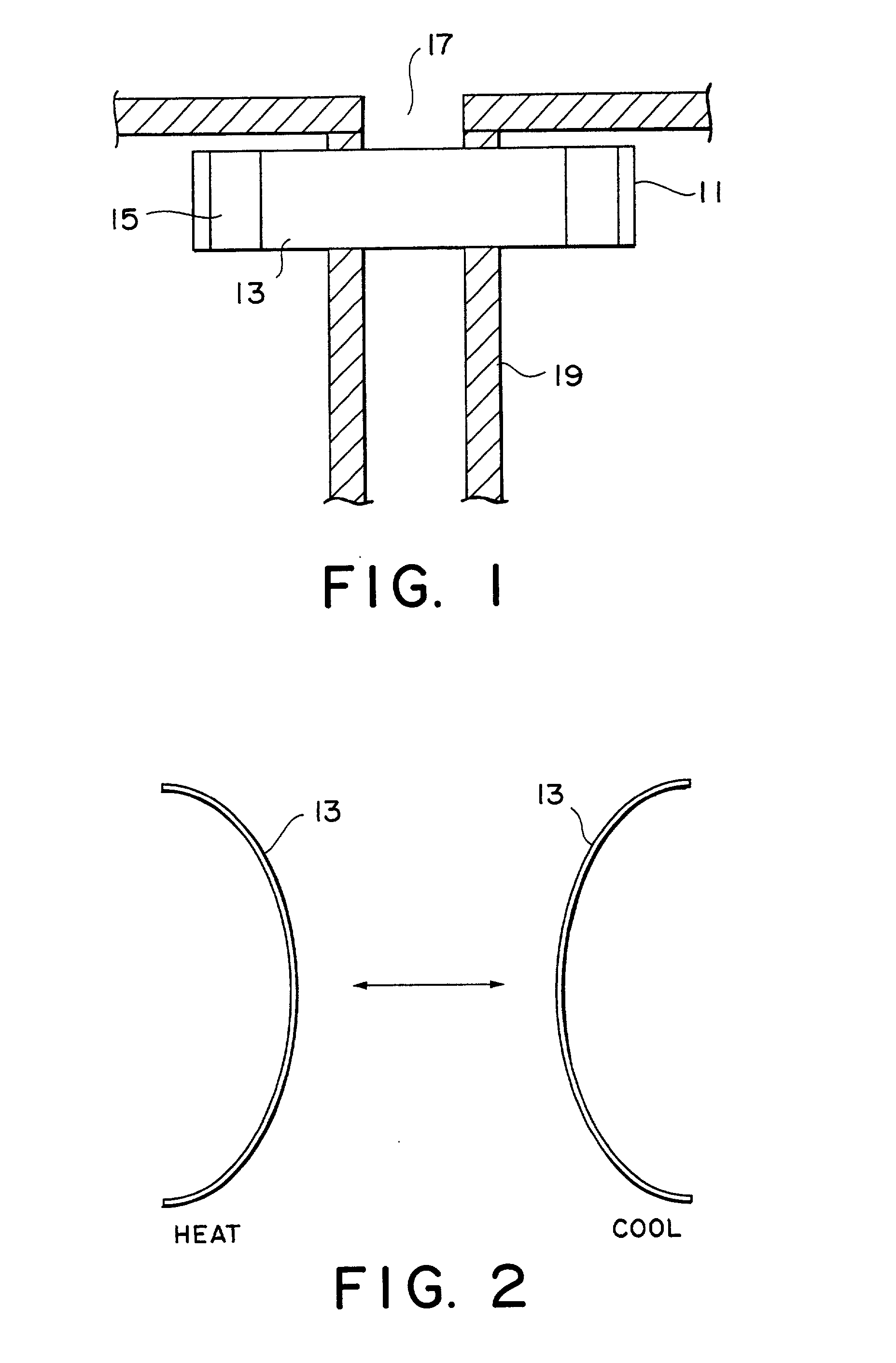
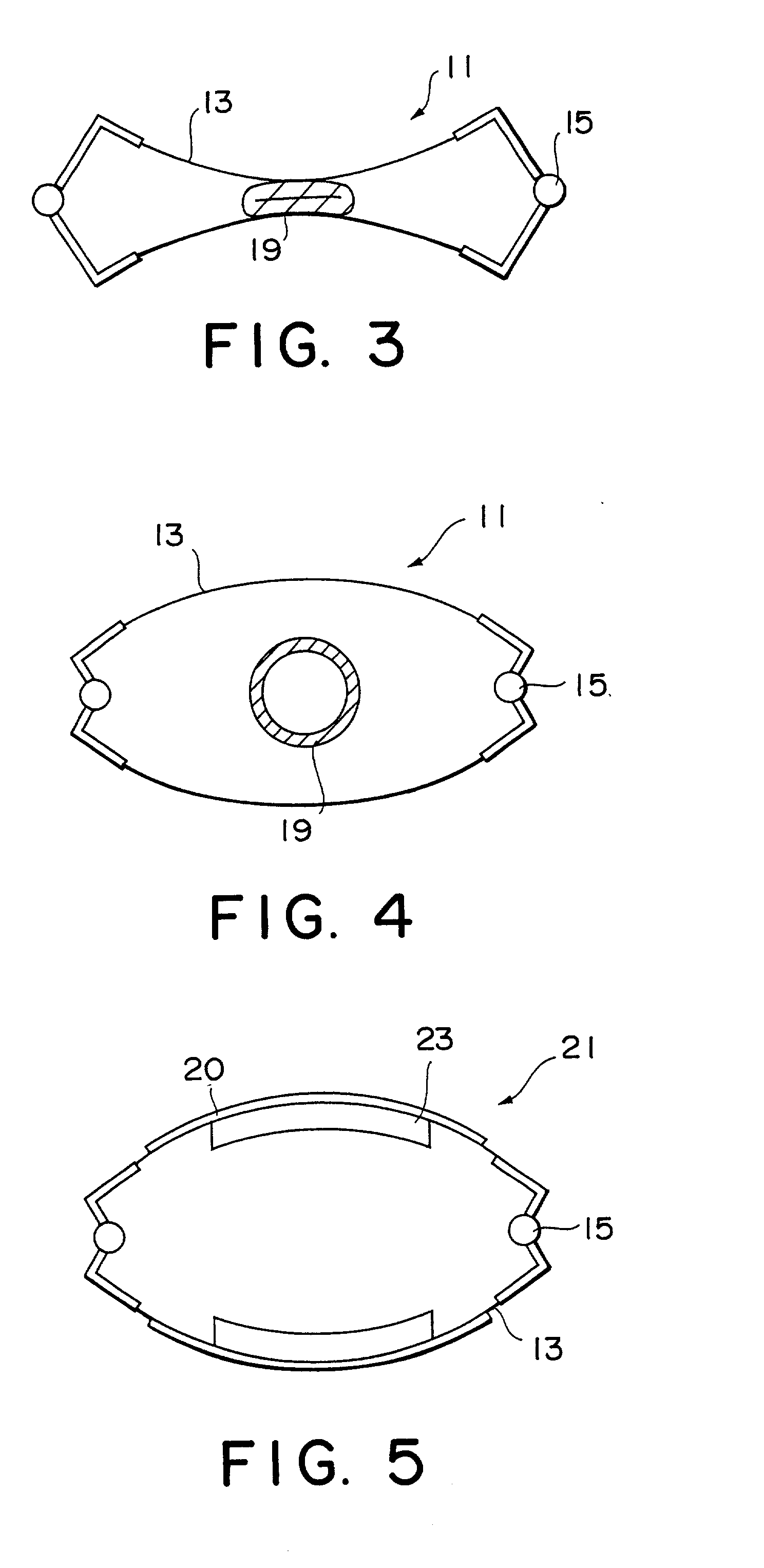
[0032] As shown in FIG. 1, an opening / closing portion 11 of an artificial sphincter according to a first embodiment comprises a pair of plate-like shape memory alloy elements (hereinafter referred to as `shape memory plates`) 13 each having a 2-way shape memory property, and hinges 15 provided so as to join together end parts of the shape memory plates 13. The opening / closing portion 11 is attached around the intestine 19 of a human or animal inside the body near to an intestinal opening 17.

[0033] For the opening / closing portion 11 of the artificial sphincter, Ti--Ni alloy plates (Ni content 50.4 at %) of thickness 0.8 mm, length 100 mm and width 20 mm are given a 2-way shape memory property. The 2-way shape memory property is obtained by subjecting the plates to solution heat treatment at 700.degree. C. for 30 minutes, and then, while restrained at a curvature of R40 mm, to aging heat treatment at 400.degree. C. for 100 hours. If heated to 40.degree. C., these plates return to the ...

second embodiment

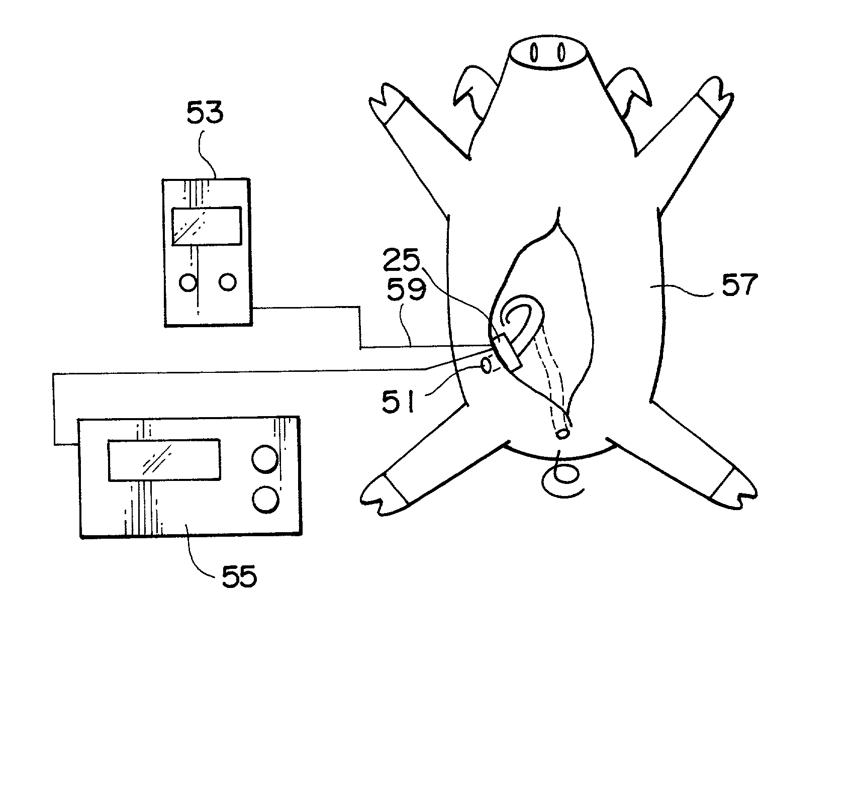
[0049] Referring to FIG. 6, an artificial sphincter according to a second embodiment of the present invention comprises a shape memory alloy opening / closing portion 25 and temperature controlling heaters 27, wherein electrical power is supplied to the temperature controlling heaters 27 by a percutaneous electrical power transmission system 33 having a coil on the side connected to the power source 53 as a primary coil 29 and a coil on the side connected to the load as a secondary coil 31. In this embodiment, the electrical power is supplied without using a lead wire.

[0050] Starting with a description of the shape memory alloy opening / closing portion 25, as shown in FIGS. 7 to 9, this opening / closing portion 25 comprises two shape memory alloy plates 35 as a pair of shape memory alloy elements that each change reversibly between two opposite shapes upon changes in temperature, and cylindrical hinges 37 that link together the end parts (at both ends) of these shape memory alloy plates...

example 1

[0069] (i) Transmission coils having amorphous magnetic wires mounted thereon were prepared as the percutaneous electrical power transmission system. Litz wire comprising bundles of 0.1 mm-diameter copper wire was used for the windings. The coils were made to be donut-shaped, which is a shape that gives excellent heat dissipation, and three thousand Co zero magnetostrictive amorphous magnetic wires of expansion diameter 20 .mu.m were mounted radially on each coil. The magnetic wires were mounted on one side only of each coil, the coils were arranged such that the surfaces on which magnetic wires were not mounted were facing one another, and electrical power was transmitted.

[0070] (ii) A rabbit (male; body weight 3 kg) was anesthetized, and the secondary coil of the percutaneous electrical power transmission system was embedded below the skin on the right side of the chest.


PUM


Abstract

With an object of providing an artificial sphincter for which repeated shape changes are possible, and for which the quantity of shape change is sufficient so as to be used as a substitute for a large natural sphincter, an artificial sphincter 11 that opens and closes, as required, either the anus of a living body or part of the intestine 19 led outside the body is provided, wherein this artificial sphincter 11 comprises a pair of shape memory alloy elements 13 that change reversibly between two opposite shapes upon changes in temperature and hinges 15 that link the shape memory alloy elements 1 together in a cylindrical shape.

Description

BACKGROUND OF THE INVENTION[0001] 1. Field of the Invention[0002] The present invention relates to an artificial sphincter used, for example, when the anal sphincter has been removed or when there has been a decline in the functioning of a sphincter.[0003] 2. Description of the Related Art[0004] Conventionally, in cases such as when development of the anal sphincter is incomplete due to infantile rectal / anal malformation or when the anal sphincter is removed due to colonic cancer as an adult, an artificial anus is used.[0005] An artificial anus commonly used conventionally is formed by sewing the intestine so as to open out at the surface of the body, and then attaching a pouch to the surface of the body so as to cover this intestinal opening.[0006] With all pouches available on the market, the whole or part of the pouch must be replaced after defecation, and an unpleasant odor may leak out. Due to such problems, there is a drawback that everyday social life becomes troublesome.[000...

Claims


Application Information

Patent Timeline
IPC IPC(8): A61F2/00A61M1/00A61F2/08A61F2/72
CPCA61F2/0036A61F2210/0033
Inventor FURUKAWA, AKIHISATAKAGI, TOSHIYUKIMATSUKI, HIDETOSHILUO, YUN
Owner TOKIN CORP
Learn More