Lighting device

Inactive Publication Date: 2002-09-19
PANASONIC CORP
View PDF0 Cites 89 Cited by
  • Summary
  • Abstract
  • Description
  • Claims
  • Application Information

AI Technical Summary

Benefits of technology

0011] Therefore, with the foregoing in mind, it is an object of the present invention to provide a lighting device where a small number of photodetectors detect the light intensity incorporating light emitted from a plurali

Problems solved by technology

However, the former method employing a phosphor has the following problems.
That is, wavelength conversion necessarily degrades the luminous efficiency.
Accordingly, this method is not preferable in terms of efficiency.
In addition, since a color of emitted light (hereafter called "luminescent color") is uniquely determined depending on the combination of wavelengths of light emitted from the LED and the phosphor, it is impossible to control the color.
Thus, if there is a change from the initial color tone due to degradation of the phosphor or the like, the color tone cannot be corrected.
Further, since the film thickness of the phosphor, the output power and the wavelength of emitted light from the LED vary to some extent in the manufacturing process, it is difficult to make the luminescent color consta

Method used


Image

  • Lighting device
  • Lighting device
  • Lighting device

Examples


first embodiment

[0044] First Embodiment

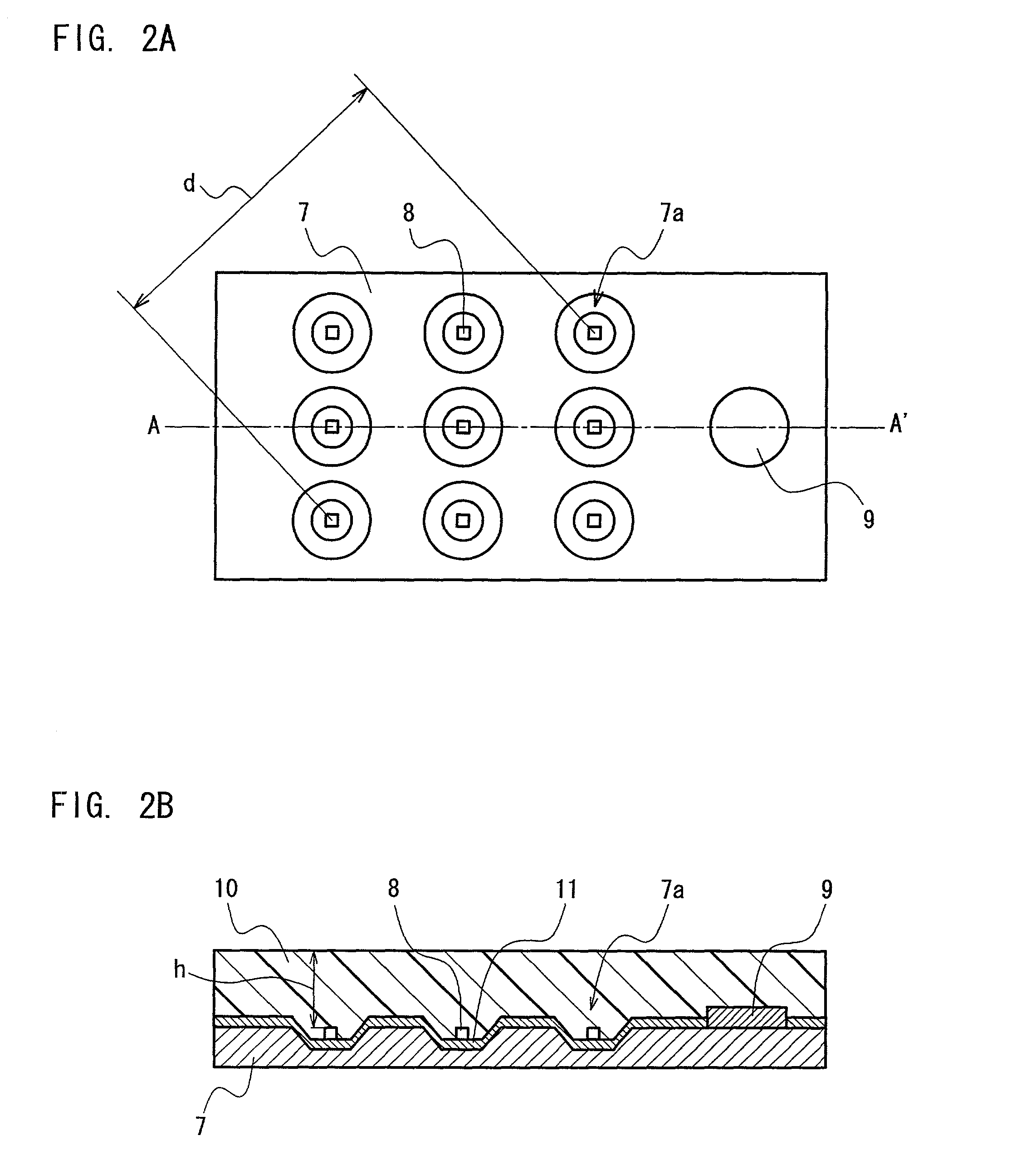
[0045] FIG. 2A is a plan view of an LED light source unit according to the first embodiment of the present invention. FIG. 2B is a cross-sectional view taken along the line A-A' in FIG. 2A. In the LED light source unit, a plurality of LEDs 8 emitting a single color of light and one photodetector 9 are mounted on a substrate 7. The LEDs and the photodetector 9 are covered with a transparent resin layer 10 so as to be integrated into one body. Since the photodetector 9 detects light propagated through the transparent resin layer 10, only one photodetector suffices with respect to a plurality of the LEDs to detect the intensity of the light emitted from the LEDs 8 adequately.

[0046] The substrate 7 preferably is made of metal so as to diffuse and dissipate heat generated by the LEDs 8 effectively. Alternatively, the substrate 7 may be made of epoxy resin or may be a composite substrate made of epoxy resin mixed with alumina. A recess 7a is formed on the substrate ...

second embodiment

[0055] Second Embodiment

[0056] FIG. 3A is a plan view of an LED light source unit according to the second embodiment of the present invention. FIG. 3B is a cross-sectional view taken along the line B-B' in FIG. 3A. In this LED light source unit, LEDs 12 to 14 that emit red, green, and blue light, respectively, are mounted on the substrate 7. These elements are covered with the transparent resin layer 10. At one end portion of the transparent resin layer 10, photodetectors 15 to 17 for each color are provided.

[0057] The photodetectors 15 to 17 are provided with spectral filters 18 to 20, respectively. These spectral filters 18 to 20 allow lights in the wavelength ranges corresponding to those emitted from the LEDs 12 to 14, respectively, to pass through, so that a photo-detecting device that deals with the respective luminescent colors is provided. With this construction, the photodetectors 15 to 17 measure the intensity distribution of the light propagated through the transparent re...

third embodiment

[0060] Third Embodiment

[0061] FIG. 4A is a plan view of an LED light source unit of the lighting device according to the third embodiment of the present invention. FIG. 4B is a cross-sectional view taken along the line C-C' in FIG. 4A. According to this embodiment, LEDs for respective luminescent colors are sequentially turned on by applying pulse voltage, so that a photodetector smaller in number than the colors can detect the intensities of multiple colors of light emitted from the LEDs.

[0062] As shown in FIGS. 4A and 4B, the LED light source unit includes LEDs 22 to 24, which emit red, green, and blue light, respectively. These LEDs 22 to 24 are covered with the transparent resin layer 10. The transparent resin layer 10 includes an optical waveguide unit 10a that extends from one side of the substrate 21 to the back portion of the substrate 21. In the vicinity of the backside of the substrate 21, a photodetector 25 is placed so as to face the end portion on the side of substrate ...


PUM


Abstract

A lighting device includes: a plurality of LEDs arranged in an at least two-dimensionally dispersed manner; a transparent resin layer that covers the plurality of LEDs in an integrated form; a photo-detecting unit that detects an intensity of light emitted from the plurality of LEDs using a photodetector, the photodetector being arranged inside, on a surface, or in the vicinity of the transparent resin layer; and a power supply circuit unit that controls driving of the plurality of LEDs based on a detection output from the photo-detecting unit. Here, the number of the photodetector is smaller than the number of the LEDs, and the photodetector detects an intensity of light emitted from the LEDs and propagated through the transparent resin layer.

Description

BACKGROUND OF THE INVENTION[0001] 1. Field of the Invention[0002] The present invention generally relates to a lighting device including a plurality of light-emitting diodes (hereafter abbreviated as "LED").[0003] 2. Related Background Art[0004] As compared with conventional light sources such as a filament lamp and a halogen lamp, LEDs have the advantage of high reliability and long life. Further, since the luminous efficiency of LEDs has been improved recently, LEDs are expected to be used as alternatives for these conventional light sources.[0005] LEDs emit light of only specific wavelengths because of their light-emitting principle. Therefore, in order to obtain white light using LEDs, an LED emitting blue light has to be combined with a phosphor which can be stimulated by the light emission of the LED to emit yellow-green light, as described in JP 2000-208815A. Alternatively, as described in JP11(1999)163412A, a plurality of LEDs that emit colored lights such as red, blue, and ...

Claims


Application Information

Patent Timeline
IPC IPC(8): F21K99/00H01L25/075H01L33/00
CPCF21K9/00H01L25/0753H01L25/167F21V23/0457H01L2924/0002H01L2924/00F21Y2113/00F21Y2115/10F21Y2113/13
Inventor TAMURA, TETSUSHINAGAI, HIDEOMATSUI, NOBUYUKISHIMIZU, MASANORI
Owner PANASONIC CORP
Why Eureka
Try Eureka