Connection verification and monitoring in optical wavelength multiplexed communications systems

Inactive Publication Date: 2002-09-26
NORTEL NETWORKS LTD
View PDF8 Cites 20 Cited by
  • Summary
  • Abstract
  • Description
  • Claims
  • Application Information

AI Technical Summary

Benefits of technology

0006] Using the multiplexer or the demultiplexer for routing the monitoring signal can save the need for individual couplers to couple a monitor signal on or off each of the optical paths of the switching element. The saving in terms of component count and cost of manufacture, as well as reduced size, can be very significant, and tends to increase as the number of wavelength demultiplexed channels in the syste

Problems solved by technology

However, such methods involve demultiplexing the data stream, to access such frame information, which may be carried out only at a terminal at the end of the path through the ne

Method used


Image

  • Connection verification and monitoring in optical wavelength multiplexed communications systems
  • Connection verification and monitoring in optical wavelength multiplexed communications systems
  • Connection verification and monitoring in optical wavelength multiplexed communications systems

Examples


Embodiment Construction

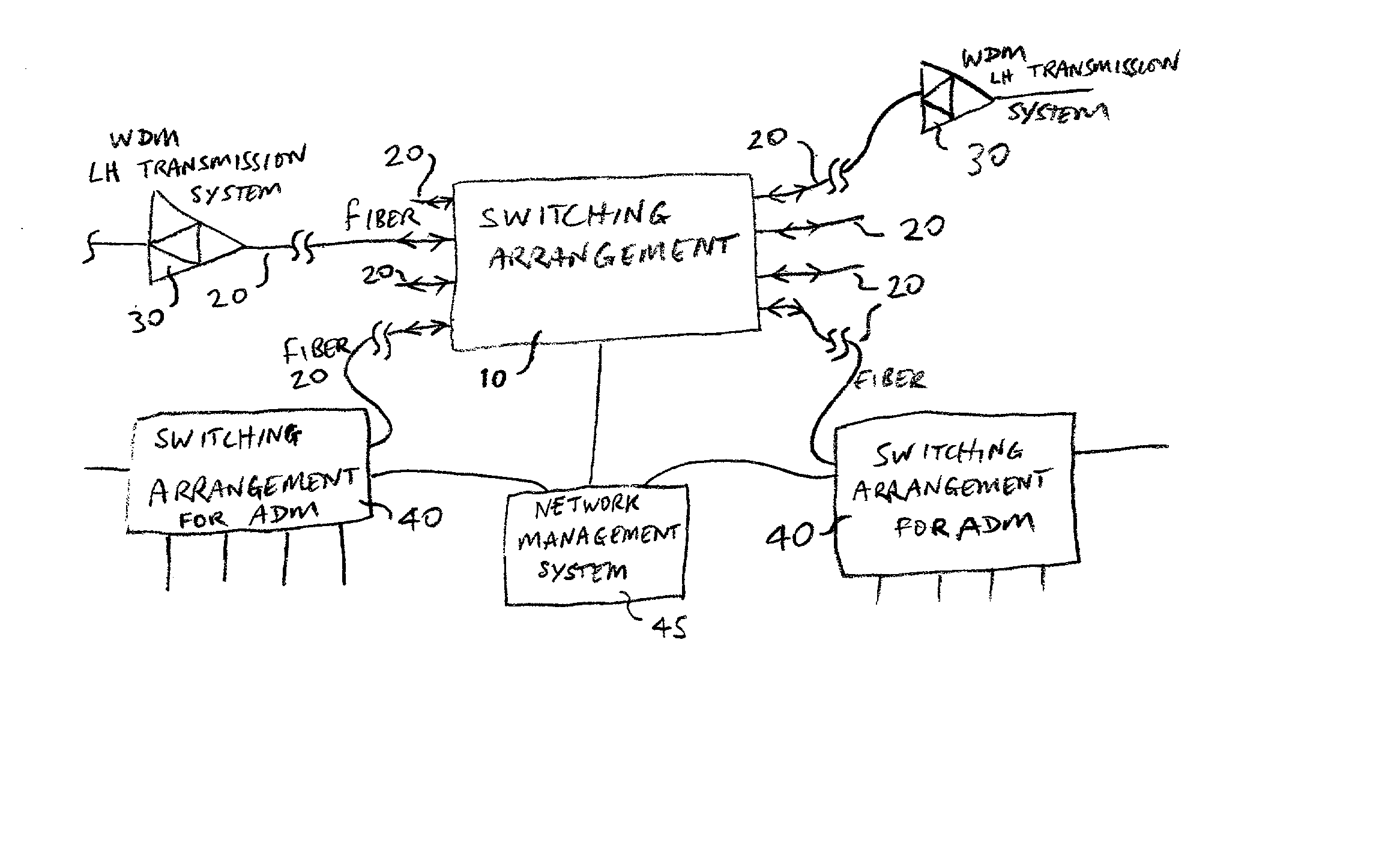
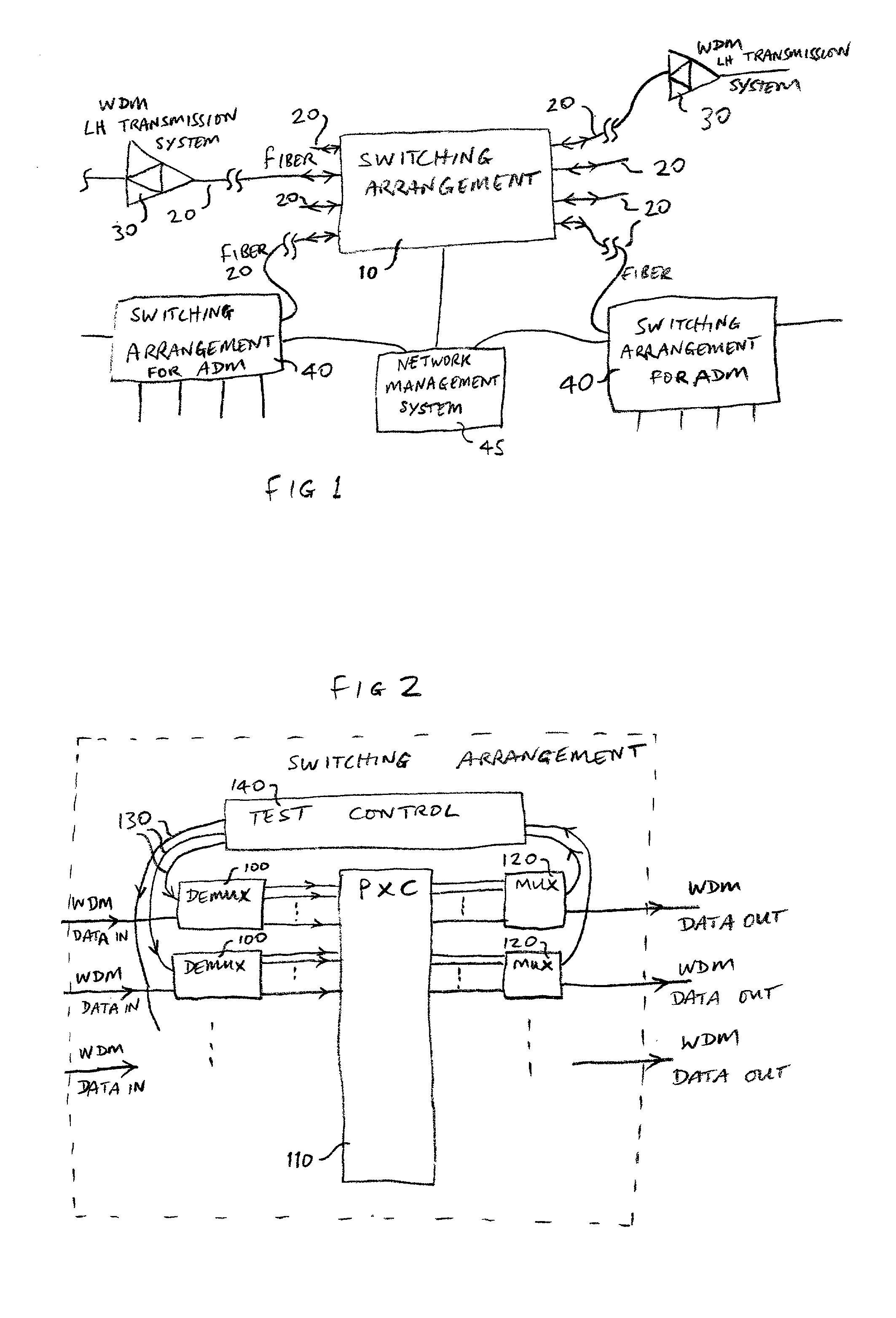
[0047] FIG. 1 shows a high level of a communications network including 10 according to a first embodiment of the invention. The switching arrangement is coupled to a number of optical fibers 20 for carrying optical signals wavelength division multiplexed together for carrying data traffic.

[0048] Four fibers are shown on each side of the switching arrangement, though there may be many more, depending on the desire to configuration of the network. In the example shown, some of the fibers are for long haul traffic, coupled to amplifiers for a WDM long haul transmission system 30. One amplifier is shown, on each side, though typically there could be many more. Some of the fibers connected to the switching arrangement (10) may be used for shorter haul transmission, typically arranged in interconnected ring networks, and coupled to add / drop multiplexers 40. These may be implemented by a switching arrangement for ADM (add / drop multiplexing) as will be described in more detail below with re...


PUM


Abstract

A wavelength demultiplexer for demultiplexing optical signals carrying data, is also used to route a separate monitoring signal on to any of the demultiplexed output paths, by changing the wavelength of the monitoring signal. This enables optical paths through a switching arrangement to be verified or tested. A multiplexer at the output of the switching arrangement may be used to detect which of the output paths of the switching element has the monitoring signal. This saves the need for individual couplers to couple a monitoring signal on to each of the inputs, and off each of the outputs of the switching element. The saving in terms of component count, cost, and reduced size increases as the number of channels increases.

Description

[0001] The invention relates to switching arrangements for optical communications networks using wavelength division multiplexing, to nodes for such networks, to optical demultiplexers for adding monitoring signals, to optical multiplexers having monitoring signal outputs, to wavelength adding nodes, to wavelength dropping nodes, to test apparatus for such switching arrangements to methods of verifying connectivity, to network management systems for controlling monitoring of optical paths, and to methods of using a demultiplexer for routing a monitoring signal.BACKGROUND TO THE INVENTION[0002] Various ways are known for testing and verifying connectivity in a communications network. Testing or verifying connectivity involves ensuring that data from one node in the network is switched or routed correctly by one or more nodes in the network, to reach its intended destination node. Such testing or verification may be carried out on an end to end basis, or at each individual node for ex...

Claims


Application Information

Patent Timeline
IPC IPC(8): H04J14/02H04Q11/00
CPCH04J14/0212H04Q11/0062H04Q2011/0069H04Q2011/0083
Inventor SPAGNOLETTI, ROBERTSPARKS, ADRIANFORBES, DUNCAN
Owner NORTEL NETWORKS LTD
Why Eureka
Try Eureka