

Electrochemical affinity assay
a technology of electrochemical affinity and affinity assay, which is applied in the field of electrochemical affinity assay, can solve the problems of not being practical in an opaque or colored fluid such as blood, and achieve the effect of reducing the redox center of the polymer and fast redox centers
- Summary
- Abstract
- Description
- Claims
- Application Information
AI Technical Summary
Benefits of technology
Problems solved by technology
Method used
Image

Examples
Embodiment Construction
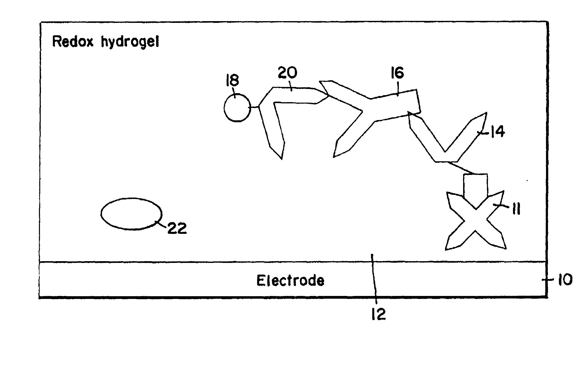
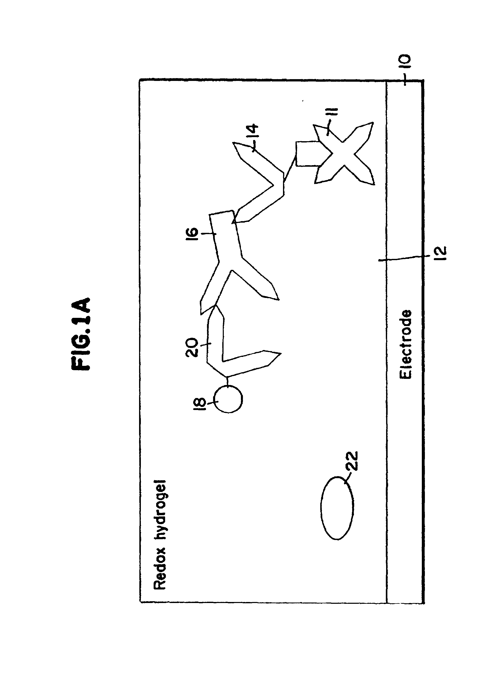
[0014] DefinitionsAs used herein, the following terms and phrases have the definitions indicated:Redox Hydrogel: The hydrated form of a crosslinked redox polymer.
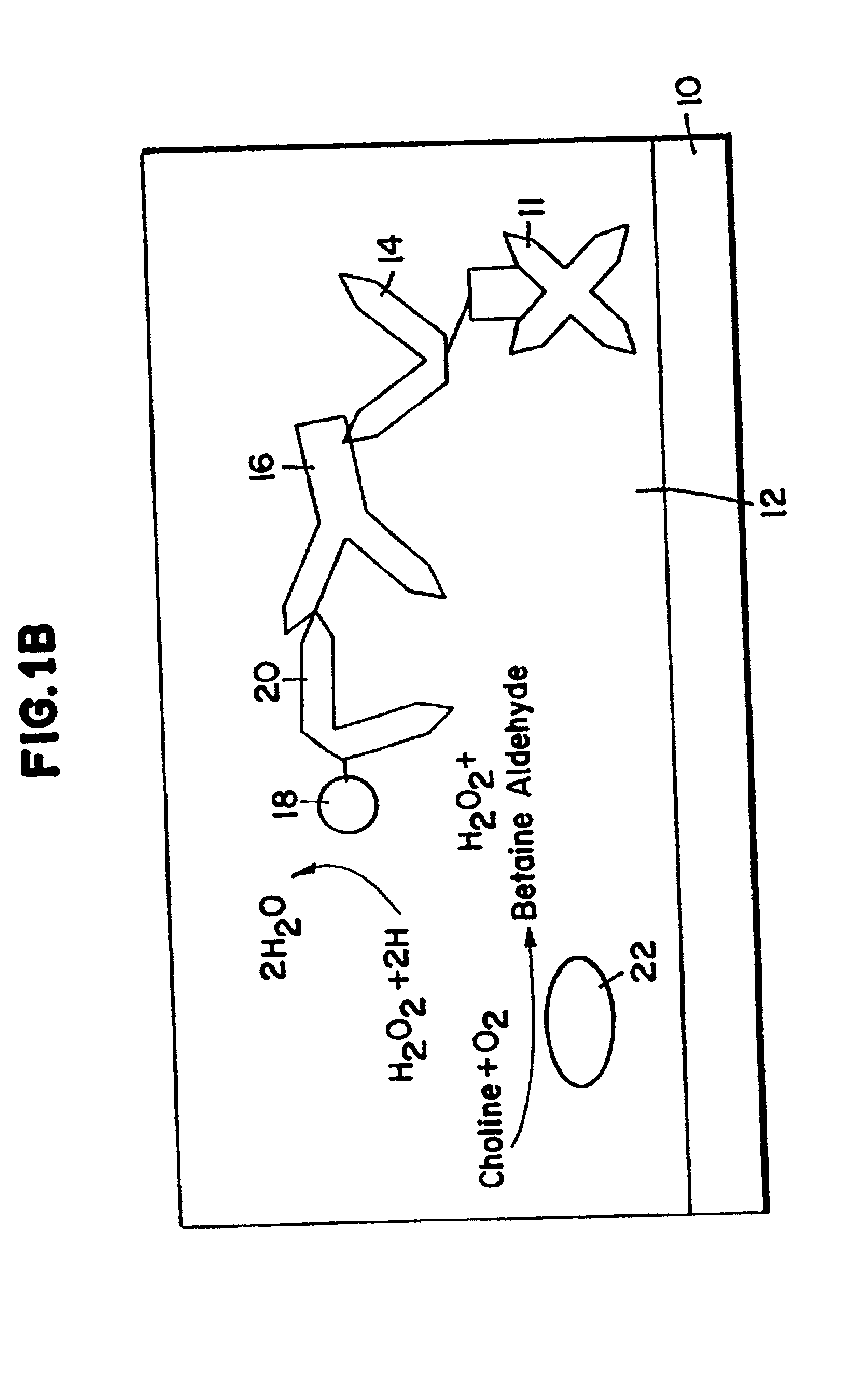
[0015] Substrate generating enzyme: An enzyme generating or producing the substrate of a detection marker, generally immobilized in the redox hydrogel. The detection marker is usually an enzyme and is covalently bound to the third member. An example of substrate generated by the enzyme is H.sub.2O.sub.2. H.sub.2O.sub.2 is generated, for example, by the substrate generating enzyme choline oxidase, which catalyzes the reaction of O.sub.2 and choline. Substrate generating enzymes that do not exchange electrons with the redox polymer at the potential where the electrode is poised are preferred. Electron exchange means transfer of electrons from the enzyme to the redox hydrogel or from the redox hydrogel to the enzyme.
[0016] Binding Agent: A macromolecular binding agent of a biomolecule. Examples of binding agents include avidin...
PUM
| Property | Measurement | Unit |
|---|---|---|
| Electric potential / voltage | aaaaa | aaaaa |
| Electric potential / voltage | aaaaa | aaaaa |
Abstract
Description
Claims
Application Information