Metal laminate structure and method for making

Inactive Publication Date: 2002-10-17
INTRL PLEX TECH INC
View PDF0 Cites 20 Cited by
  • Summary
  • Abstract
  • Description
  • Claims
  • Application Information

AI Technical Summary

Problems solved by technology

Accordingly, while the limitations of prior art structures used in computer disk drives is presented as an exemplary application for the laminate structures of the present invention, the limitations inherent in prior art monolithic (i.e., non-laminate) structures, particularly in regard to their vibrational properties, similarly limits the performance of prior art structures in other applications.
Such shock l

Method used


Image

  • Metal laminate structure and method for making
  • Metal laminate structure and method for making
  • Metal laminate structure and method for making

Examples


Embodiment Construction

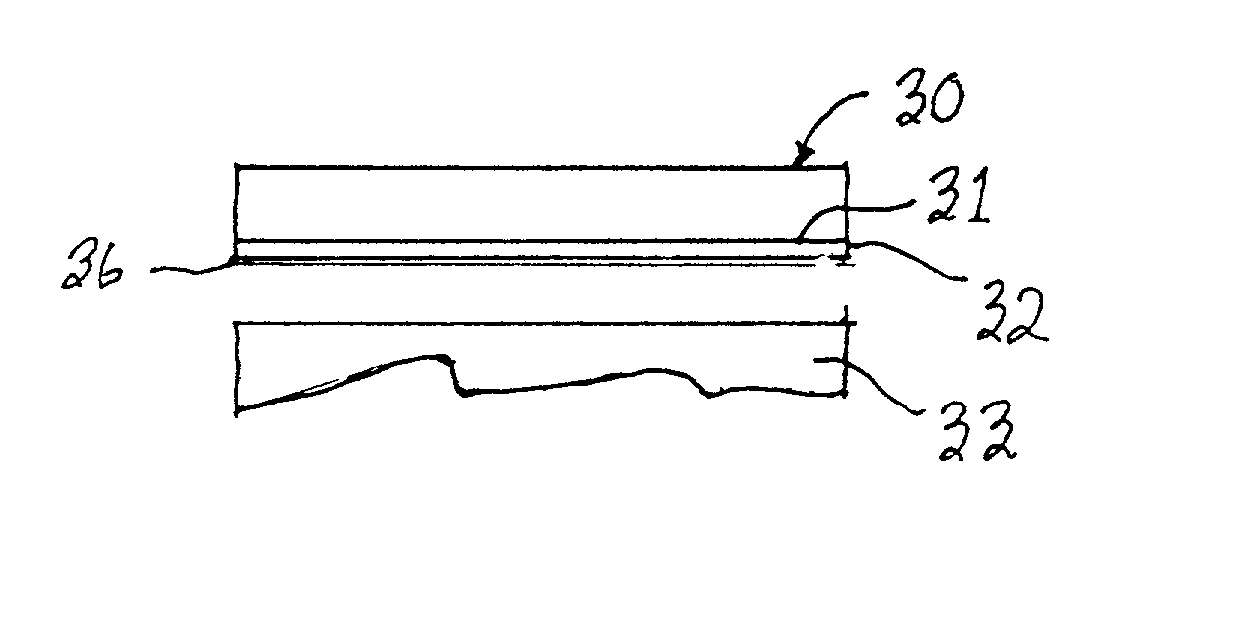
[0038] Two strips of 0.005" thick 301 stainless steel (SS) were plated on one side with a layer of copper using an electrolytic process. On both strips, the thickness of the copper plating was 5 microns. The strips were then sectioned to have a length and a width of 3" and 2", respectively. A 0.010" thick sheet of Mg dimensioned to have the same length and width as the strips was interposed between the copper-plated surface of the two strips and the structure placed in a vacuum hot press. Stainless steel platens measuring 3.75" in diameter were placed on both sides of the structure to ensure a uniform application of pressure to the metal strips. The chamber was then evacuated to a pressure of 50 microns of Hg and backfilled with gettered Argon to a pressure of 10" Hg. The process was then repeated to ensure that a majority of the oxygen was removed from the hot-press chamber.

[0039] The unconsolidated structure was heated to a temperature of 200.degree. C. for 0.5 hours to allow any ...


PUM

PropertyMeasurementUnit
Fractionaaaaaaaaaa
Frequencyaaaaaaaaaa
Frequencyaaaaaaaaaa

Abstract

Laminates consisting of a high-damping core material sandwiched between two stiff, weldable skins. The laminate structures have increased resonant frequencies, improved damping characteristics, do not outgas, and may have a decreased inertial moment. The laminates are comprised of 100% metal constituents, and do not rely on epoxy or low-melting point solders. To make the laminate structures, a first alloyable metal is deposited on the surface of a dissimilar metal. The coated surface is then placed in contact with a second alloyable metal and allowed to interdiffuse at elevated temperatures. The metals are chosen such that diffusion creates an alloy with a melting point lower than either of the constituents. The processing temperature is set so that the alloy melts but leaves the base metals in solid form, causing a thin layer of liquid to form and wet both sides of the interface. External pressure is applied to the opposing base metals in such a way as to induce flow of the liquid layer and disrupt any oxide layers present on the surface of one or more of the base metals. Continued diffusion elevates the melting temperature of the liquid phase and causes it to solidify isothermally, creating a bond between the base metals. Highly polished surfaces on the base metals comprising the laminate structure are not required because the applied pressure causes the metal (in thin sheet form) to deform and create the intimate metal-metal contact necessary for diffusion. Moreover, the liquid flow helps to fill gaps between the parent materials and further mitigates the need for polished surfaces.

Description

[0001] 1. Field of the Invention[0002] Laminate structures having improved dynamic properties, specifically increased resonant frequencies and higher damping, and more particularly laminate structures comprising weldable metals and a method for making the laminates.[0003] 2. Prior Art[0004] The need for laminate structures made in accordance with the present invention is exemplified by discussing the performance limitations of structures made in accordance with the prior art in a representative application. Accordingly, while the limitations of prior art structures used in computer disk drives is presented as an exemplary application for the laminate structures of the present invention, the limitations inherent in prior art monolithic (i.e., non-laminate) structures, particularly in regard to their vibrational properties, similarly limits the performance of prior art structures in other applications. Although the present invention is discussed in the context of a particular applicat...

Claims


Application Information

Patent Timeline
IPC IPC(8): B23K20/02
CPCB23K20/023Y10T428/12979B23K2203/12B23K2203/10B23K2103/10B23K2103/12
Inventor BRINK, DAMON
Owner INTRL PLEX TECH INC
Why Eureka
Try Eureka