
Chamber for and a method of processing electronic devices and the use of such a chamber

a technology of electronic devices and chambers, which is applied in the field of mobile telephone testing, can solve the problems of increasing the testing time and wear of emc gaskets, time-consuming tasks, and one-time-consuming testing of electronic devices, so as to reduce the testing time per unit, reduce the wear of the test chamber, and save time

Inactive Publication Date: 2002-10-31
TELEFON AB LM ERICSSON (PUBL)
View PDF7 Cites 127 Cited by
  • Summary
  • Abstract
  • Description
  • Claims
  • Application Information

AI Technical Summary

Benefits of technology

[0016] An advantage of the invention is that many devices are tested simultaneously (decreases testing time per unit, reduces wear of the test chamber). The chamber may e.g. be used for production test of high volume devices.
[0017] When said chamber is a climatic chamber, it is ensured that the processing may be performed at different climatic conditions, e.g. according to a specification to comply with a specific standard or quality requirements. Environmental parameters such as temperature, humidity, pressure, atmosphere (air, specific gases or fluids, specific pH, etc.) may be varied. An example of the use of the invention is in connection with the testing of radio properties of devices over temperature, in which case e.g. performing temperature cycling on many devices simultaneously is of great advantage by saving time.
[0018] When said chamber is electromagnetically shielded, it is ensured that the processes carried out in the chamber are not disturbed by electromagnetic noise from the environment, which increases the reliability of measurements in the chamber. Further, it prevents possible electromagnetic noise from the activities in the chamber from reaching the environment.
[0019] When said chamber is anechoic, it is ensured that reflections from the walls of the chamber are minimized, which is of importance to some acoustic and electromagnetic measurements.
[0020] When said chamber is echoic, it is ensured that reflections from the wall create a multi-path environment in the chamber, thus contributing to the homogeneity of the acoustic or electromagnetic field distribution in the chamber.
[0021] When said chamber comprises at least one mode stirrer, it is ensured that the acoustic or electromagnetic field distribution becomes randomised, approximating a homogeneous and isotropic field distribution inside the chamber, creating a so-called mode-stirred chamber (MSC) or reverberation chamber. In other words, the field strength is approximately "the same" in all points of the chamber and independent of direction. This has e.g. obvious advantages in the case of a mode-stirred chamber for measuring radio properties of mobile communications devices by removing the need for the development of special test fixtures for each different type of device (because the orientation of the devices becomes less significant), reducing costs. Further, the measurements are relatively independent of the location of the devices and of the direction of the antennas, making the chamber well suited for handling several devices simultaneously under approximately identical field conditions. The mode- stirred chamber has been extensively used in connection with measurements concerning electromagnetic compatibility (EMC), and its properties are well understood.

Problems solved by technology

This is a time-consuming task, however.
The problem of the prior art is that the testing of the electronic devices is done one at a time in a test fixture.
This increases testing time and the wear of the EMC gaskets, etc.
It is complicated (time-consuming and thus expensive) to make environmental tests at the same time as testing other properties, e.g. testing radiated power from an antenna of a mobile telephone at extreme temperatures because each device must be temperature cycled individually.
Further, and economically importantly, no undesired tapping of the information is possible during the downloading process.
The important issue is that the device under test has sufficient energy for the relevant test to be carried out.
Often, electronic devices are only of value when the software is present, i.e. the `naked` devices are not interesting objects for theft.
Existing SAR test equipment is very expensive and has a long delivery time from the producers of such equipment.

Method used


Image

  • Chamber for and a method of processing electronic devices and the use of such a chamber
  • Chamber for and a method of processing electronic devices and the use of such a chamber
  • Chamber for and a method of processing electronic devices and the use of such a chamber

Examples


Embodiment Construction

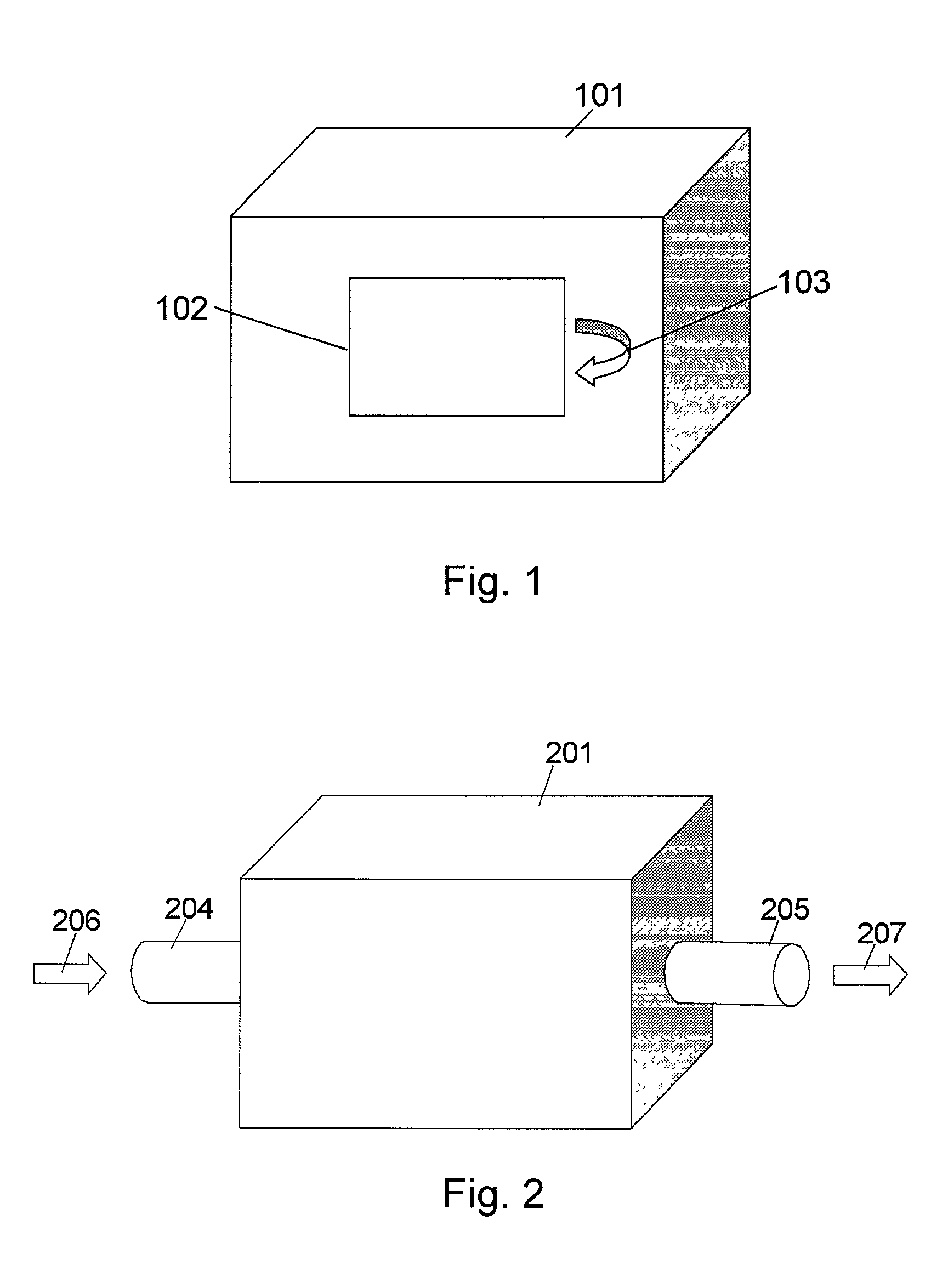
[0089] FIG. 1 shows a mode-stirred chamber 101 with an EMC door 102, which is to be opened outwards 103.

[0090] A batch of electronic devices can be positioned in the mode-stirred chamber 101 for simultaneous testing and / or simultaneous software download. The electronic devices enter the mode-stirred chamber 101 through the EMC door 102. The EMC door 102 has shielding properties for radiation between the exterior and the interior of the mode-stirred chamber 101.

[0091] FIG. 2 shows a mode-stirred chamber 201 with two openings made as waveguides 204, 205. The waveguide 204 is an entry 206, and the waveguide 205 is an exit 207.

[0092] Electronic devices continuously or discontinuously flow into the mode-stirred chamber 201 through the waveguide 204, through the mode-stirred chamber 201, and finally out through the waveguide 205. During the period the electronic devices are inside the mode-stirred chamber 201, simultaneous testing and / or simultaneous software downloading takes place for t...


PUM


Abstract

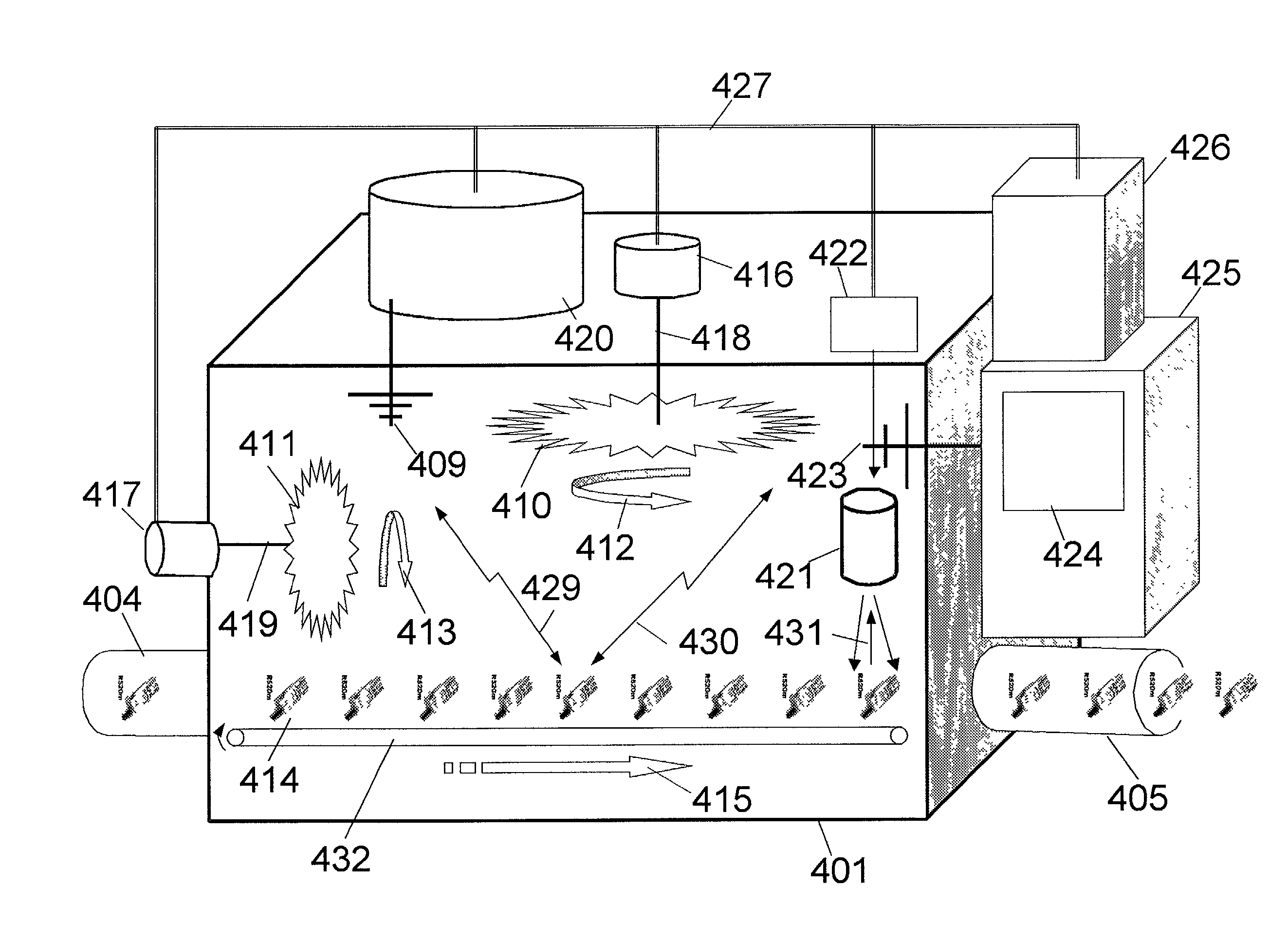
The invention relates to: A chamber (101, 201, 301, 401) for processing electronic devices (414), the use of such a chamber and a method. The object of the present invention is to provide a flexible system for and method of decreasing the processing time per unit of electronic devices during production and test, thus reducing costs. The problem is solved in that the chamber (101, 201, 301, 401) is adapted for handling several devices (414) simultaneously and said processing comprises a transfer of airborne signals (429, 430, 431). This has the advantage of allowing a simultaneous test under controlled and homogeneous conditions. The invention may be used in the production and test of electronic devices such as mobile communications devices.

Description

[0001] The present invention relates to the production and test of electronic devices.[0002] The invention relates specifically to: A chamber for processing electronic devices.[0003] The invention furthermore relates to: A method of processing electronic devices.[0004] The invention furthermore relates to: The use of a chamber for processing electronic devices.DESCRIPTION OF RELATED ART[0005] The following account of the prior art relates to one of the areas of application of the present invention, test of mobile telephones.[0006] The production of electronic devices such as mobile telephones in large volumes brings focus on all aspects of the development and production process in order to improve quality, decrease processing times and reduce costs to follow the pace of the market.[0007] One aspect of this is the testing of devices. To ensure constant quality, devices must be individually tested and preferably under different environmental conditions. This is a time-consuming task, ...

Claims


Application Information

Patent Timeline
IPC IPC(8): G01R29/08G01R29/10G01R31/28G01R35/00H04B17/00H04Q7/34
CPCG01R29/0821G01R35/00G01R31/2849G01R29/105
Inventor PERSSON, ANDERSMADSEN, KENTBERGSTEDT, HANS
Owner TELEFON AB LM ERICSSON (PUBL)
Learn More