Circuit arrangement for the power supply of protective devices for the passengers of a vehicle

Inactive Publication Date: 2002-12-05
ROBERT BOSCH GMBH
View PDF13 Cites 12 Cited by
  • Summary
  • Abstract
  • Description
  • Claims
  • Application Information

AI Technical Summary

Problems solved by technology

The passenger protection systems installed in motor vehicles--these include airbags, seat belts, etc.--are becoming more and more complex over time.
In the future, due to the necessary complexity of the protective devices, there will be more than 20 triggering circuits for triggering the individual restraint devices.
In the event of multiple impacts, if a time delay is necessary during th

Method used


Image

  • Circuit arrangement for the power supply of protective devices for the passengers of a vehicle
  • Circuit arrangement for the power supply of protective devices for the passengers of a vehicle

Examples


Embodiment Construction

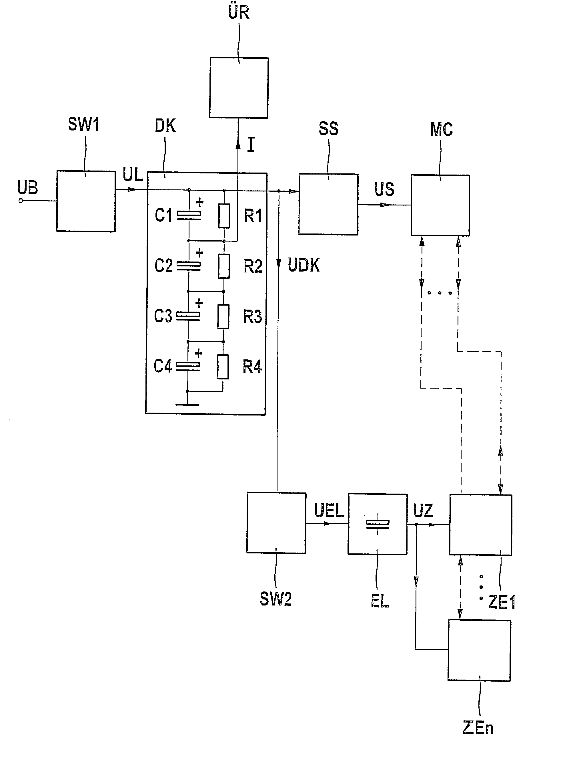
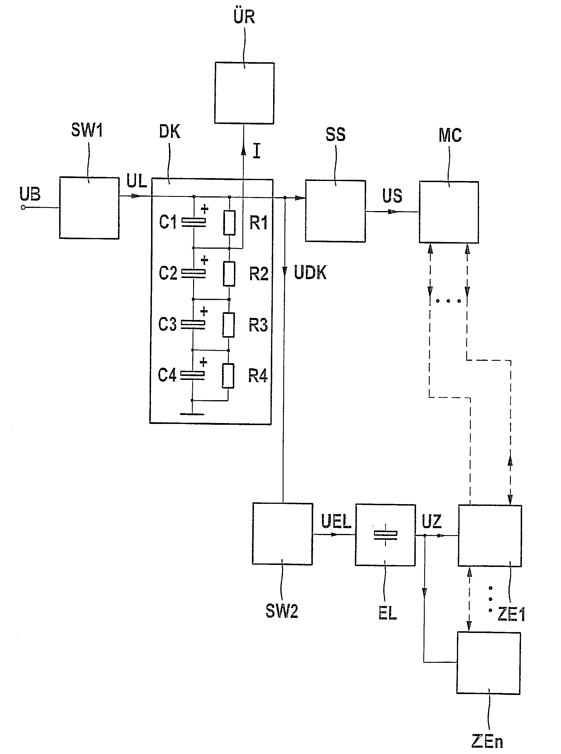
[0011] A block diagram of a circuit arrangement is illustrated in the drawing which supplies energy to multiple trigger power modules ZE1, . . . , ZEn of n restraint devices in a vehicle and a signal processor SP, which drives these trigger power modules.

[0012] The circuit arrangement for the power supply shown has a first energy store DK in the form of four double-layer capacitors C1, C2, C3, and C4 connected in series. Required charging voltage UL (e.g., 8.8 + / -0.4 V) for the series circuit of double-layer capacitors C1, . . . , C4 is made available by a voltage transformer SW1 (step up / step down voltage transformer) from battery voltage UB supplied by the vehicle battery.

[0013] The design and the properties of double-layer capacitors are described in U.S. Pat. No. 5,621,607. The electrodes of these double-layer capacitors are made of a composition of aluminum and carbon and therefore produce a relatively low internal ohmic resistance of the capacitor. A diluted sulfuric acid, for...


PUM


Abstract

In order that the circuit arrangement ensures a high availability of the protective functions of all necessary passenger protection devices, it comprises multiple double-layer capacitors (C1, C2, C3, C4) connected in series and an electrolytic capacitor (EL), which obtains its charge from the double-layer capacitors (C1, C2, C3, C4), which have a higher capacitance but a lower nominal voltage than the electrolytic capacitor (EL). The electrolytic capacitor (EL) exclusively supplies the triggering voltage (UZ) necessary for the trigger power modules (ZE1, . . . , ZEn) of the protective devices.

Description

BACKGROUND INFORMATION[0001] The present invention relates to a circuit arrangement for the power supply of protective devices for vehicle passengers, having a capacitor arrangement which provides the energy necessary for triggering the protective devices.[0002] The passenger protection systems installed in motor vehicles--these include airbags, seat belts, etc.--are becoming more and more complex over time. Particularly the number of airbags installed in vehicles is becoming ever greater. The restraint devices are to be triggerable in multiple sequential stages in order to offer protection to the passengers even in the event of multiple sequential impacts. In the future, due to the necessary complexity of the protective devices, there will be more than 20 triggering circuits for triggering the individual restraint devices.[0003] In order that all of the restraint devices present in the vehicle can still be activated in the event of a crash even if the power supply in the vehicle is...

Claims


Application Information

Patent Timeline
IPC IPC(8): B60R16/02B60R21/01B60R21/16H02J7/34
CPCH02J7/345B60R21/017
Inventor MATTES, BERNHARD
Owner ROBERT BOSCH GMBH
Why Eureka
Try Eureka