Shredder dust feeding device, reverberatory furnace provided with this feeding device, and furnace for burning shredder dust

a technology for shredder dust and feeding device, which is applied in the direction of furnaces, combustion types, charge manipulation, etc., can solve the problems of limited amount of shredder dust to be processed in the reverberatory furnace 1 and society's problems, and increase the amount of off-gases

Inactive Publication Date: 2002-12-26
ONAHAMA SEIREN
View PDF3 Cites 12 Cited by
  • Summary
  • Abstract
  • Description
  • Claims
  • Application Information

AI Technical Summary

Problems solved by technology

In recent years the processing of industrial waste materials has become a problem for society.
One of these problems was that the amount of shredder dust to be processed in the reverberatory furnace 1 was limited by the volume of off-gas expelled from the reverberatory furnace 1.
However, for example, if the feeding chute is simply installed in the ceiling of the reverberatory furnace 1 and the shredder dust simply fed into this chute, the off-gases increase and in cases in which it is not possible to maintain a sufficient negative draft inside the reverberatory furnace 1, there is the concern that the gas inside the furnace will leak out by the feeding chute.
Since the ceiling needs to be so secure that the gas inside the furnace does not leak even when the shredder dust is being fed, it is necessary to provide a double-damper, for example, which results, of course, in the operation of feeding the shredder dust becoming complicated, but also means that continuous feeding is difficult.
The ultimate result is that restrictions are placed on the amount of shredder dust that can be processed.
Another problem is that if shredder dust remains as unburnt condition when the shredder dust is charged to the reverberatory furnace 1, this unburnt shredder dust piles up in the reverberatory furnace 1 forming small hills (piles) in the furnace.
As a result, when new shredder dust is fed to the top of the pile, the hot-gas goes out of the reverberatory furnace 1 through the feeding chute positioned directly above the pile, creating the concern that the conveyor belt used for transporting the shredder dust may be burnt.
Moreover, particularly if these large piles are formed nearby the burners inside the reverberatory furnace 1, then the burning condition of the burners is disturbed which naturally results in the burning of the shredder dust not being possible, and also results in the burner combustion heat not being able to be used effectively for melting copper concentrates.

Method used


Image

  • Shredder dust feeding device, reverberatory furnace provided with this feeding device, and furnace for burning shredder dust
  • Shredder dust feeding device, reverberatory furnace provided with this feeding device, and furnace for burning shredder dust
  • Shredder dust feeding device, reverberatory furnace provided with this feeding device, and furnace for burning shredder dust

Examples


first embodiment

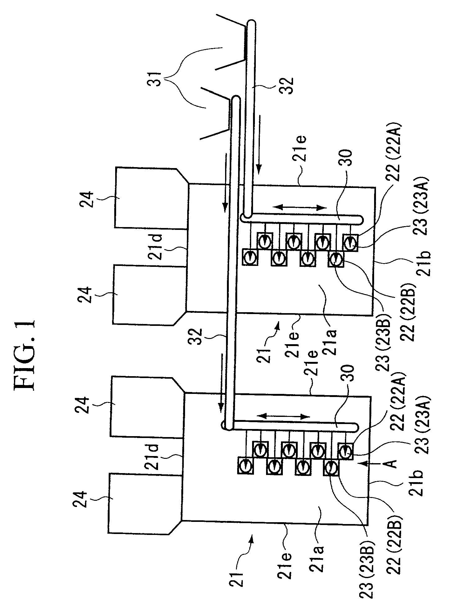
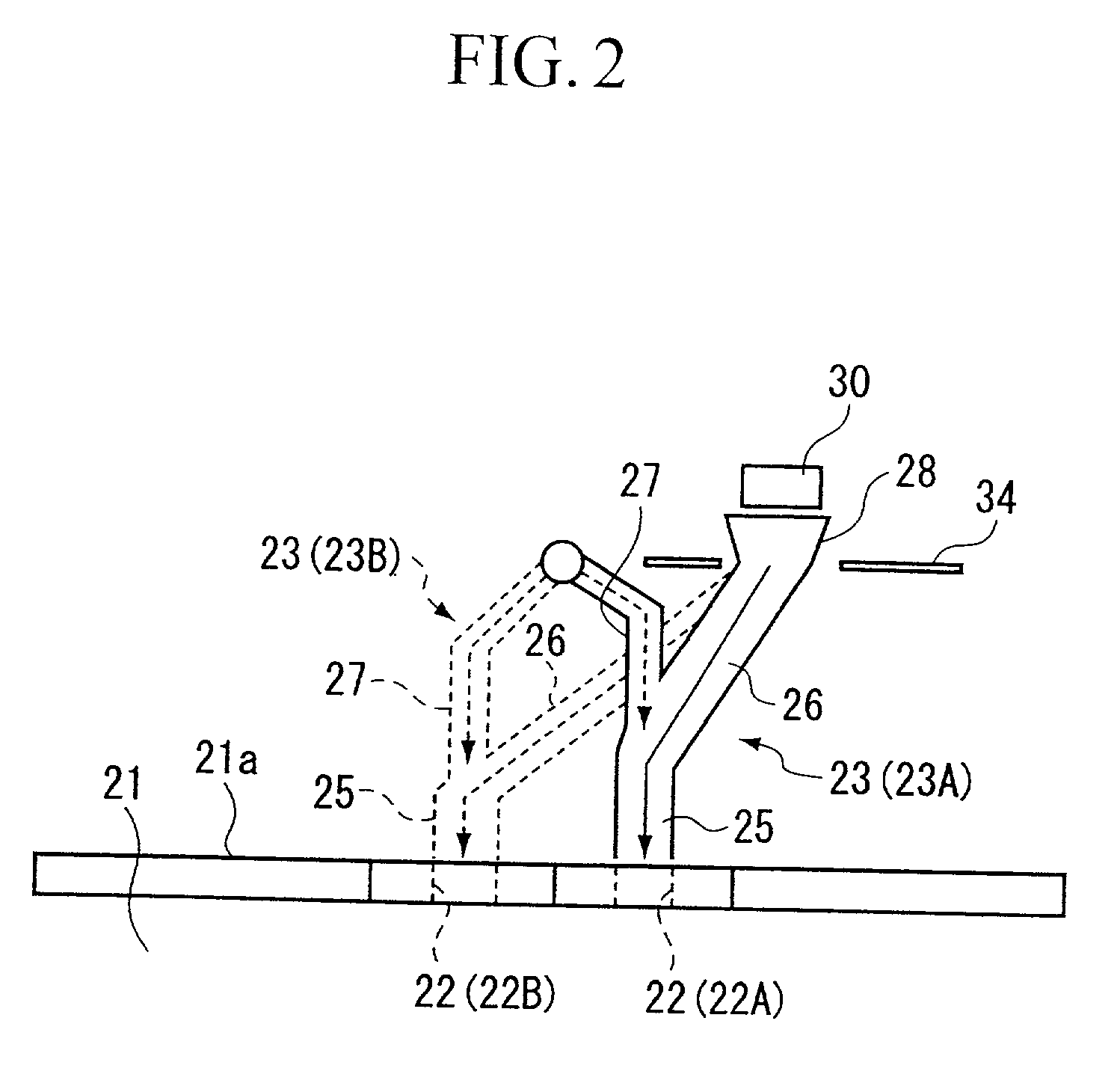
[0041] FIGS. 1 through 8 show the present invention. In this embodiment, the present invention is applied to a green charge type (wet charge type) of reverberatory furnace 21 used for smelting copper concentrates. In the present embodiment, as is shown in FIG. 1, reverberatory furnaces 21 and 21 are provided in parallel and eight feeding ports 22 are provided in each ceiling portion 21a of the reverberatory furnaces 21 and 21. As is shown in FIG. 2, a shredder dust feeding facilities 23 is provided for each of the feeding ports 22. As is shown in FIG. 1 and in FIGS. 3 to 5, as seen in plan view, the reverberatory furnaces 21 are formed in a substantially elongated schematic box shape and one end side in the longitudinal direction thereof (i.e. the bottom side in FIG. 1 and the right side in FIGS. 3 and 4) is the side where the burner is provided. A plurality of window portions 21c for burner installation are formed in the wall portion 21b of the one end side in the longitudinal dire...

second embodiment

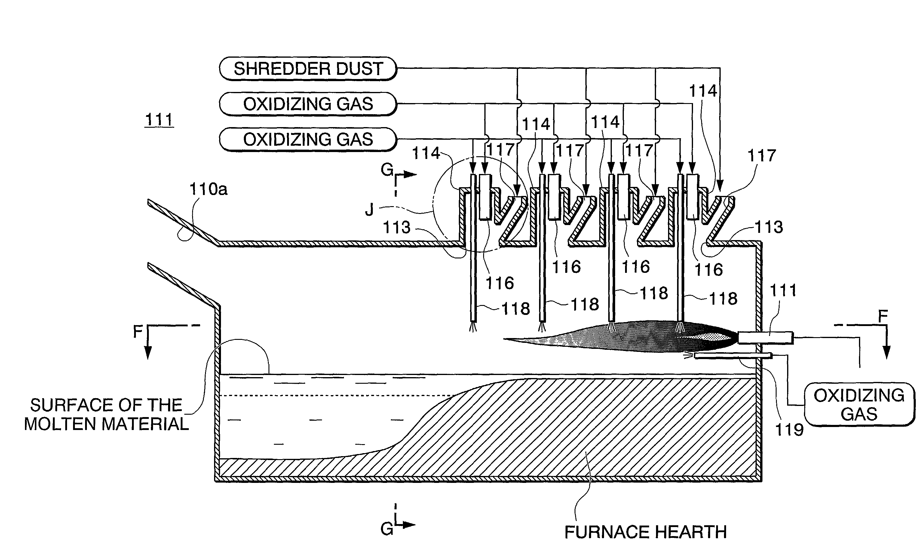
[0057] The object of the second embodiment will be explained referring to FIG. 9. In a reverberatory furnace shown in FIG. 9, a flame is emitted from a burner provided on the wall on one side of the furnace body 101 that uses coal or heavy oil as a fuel, and thereby the interior of the furnace body 101 is heated. Next, the interior of the furnace body 101 is fed with raw material to be smelted from a raw material feeding opening (not illustrated) provided on both sides of the ceiling at one end of the furnace body 101. In addition, inside the furnace body 101, the shredder dust is fed via a fuel and gas feeding opening 103 by the dust feeding chute 107 connected to the main feeding chute 104 installed in the fuel and gas feeding opening 103, which is provided at the center of the ceiling on one side. In order to add the shredder dust fuel, a compressed oxidizing gas is blown from a first feeding chute 106 provided inside the main feeding chute 104 installed on the fuel and gas feedi...


PUM

PropertyMeasurementUnit
thicknessaaaaaaaaaa
thicknessaaaaaaaaaa
inner diameteraaaaaaaaaa

Abstract

The present invention relates to a device for feeding shredder dust to a furnace such as a reverberatory furnace. This device comprises a feeding chute that passes to the inside of the reverberatory furnace and is fitted to the ceiling of the reverberatory furnace. Shredder dust can be fed from this feeding chute which also allows oxygen enriched air to be supplied to the feeding chute and fed to the inside of the reverberatory furnace. Further, the present invention relates to a reverberatory furnace in which a burner is able to be installed in a wall portion of one end side thereof. A plurality of feeding ports to which are connected the feeding chutes of the shredder dust feeding devices are provided at the one end side in the ceiling portion thereof forming a plurality of staggered rows facing the other end side.

Description

[0001] This is a continuation-in-part application of application Ser. No. 09 / 896,203 filed on Jun. 29, 2001.[0002] 1. Field of the Invention[0003] The present invention relates to a feeding device for shredder dust for performing an incinerating process by burning shredder dust comprising various shredded waste materials by feeding the shredder dust to a furnace such as a reverberatory furnace for non-ferrous smelting and to a furnace provided with this feeding device.[0004] 2. Description of the Related Art[0005] In recent years the processing of industrial waste materials has become a problem for society. Currently, the landfilling of waste materials is severely restricted and incineration methods are also regulated so as to prevent dioxin from being generated. In this situation, in order to recover various metals such as copper, gold, silver, and, palladium without generating dioxin, the inventors of the present invention attempted the processing of automobile shredder dust in a ...

Claims


Application Information

Patent Timeline
Patent Type & Authority Applications(United States)
IPC IPC(8): C22B7/00C22B7/02F27B3/02F27B3/18F27B3/20F27D3/10F27D3/18
CPCC22B7/003C22B7/02F27B3/02F27D3/18F27B3/205F27D3/10F27B3/18Y02P10/20
Inventor NISHIWAKI, MICHIOTOBE, KIYOMISATO, TAKAYUKISUZUKI, KAORUISHIKAWA, SHIGERU
Owner ONAHAMA SEIREN
Why Eureka
Try Eureka