Thermal bond verification

a technology of thermal bonds and verification methods, applied in the field of systems and methods for evaluating thermal bonds, can solve the problems of difficult or expensive verification of the good thermal bond of all items manufactured, affecting dramatically the operation of the thermal bond, and difficult to verify

Inactive Publication Date: 2002-12-26
SBS TECH
View PDF0 Cites 20 Cited by
  • Summary
  • Abstract
  • Description
  • Claims
  • Application Information

AI Technical Summary

Problems solved by technology

A heat-conducting substance is typically a non-Newtonian fluid that may be tacky and flexible, at least when installed, so that it fills most of the microscopic gaps between the surfaces of the heat-producing device and heat-absorbing apparatus.
However, as with any manufacturing process, it is difficult or expensive to verify that all items manufactured have a good thermal bond.
There is typically a relatively small area on the top of the chip that may need to have a low resistance path to the heat sink and modifications to this area (e.g. drilling to insert a temperature probe) may dramatically affect its operation.
Due to the mechanical arrangement of the two parts (CPU and heat sink) as well as the complexities encountered when trying to remove heat from CPUs in confined spaces, in the past it has been difficult to verify during manufacture that the thermal bond between the CPU and the heat sink has been correctly made.
The calculating procedure may be performed by the device, and may involve dividing by the power consumption of the device.

Method used


Image

  • Thermal bond verification
  • Thermal bond verification
  • Thermal bond verification

Examples


exemplary embodiment 100

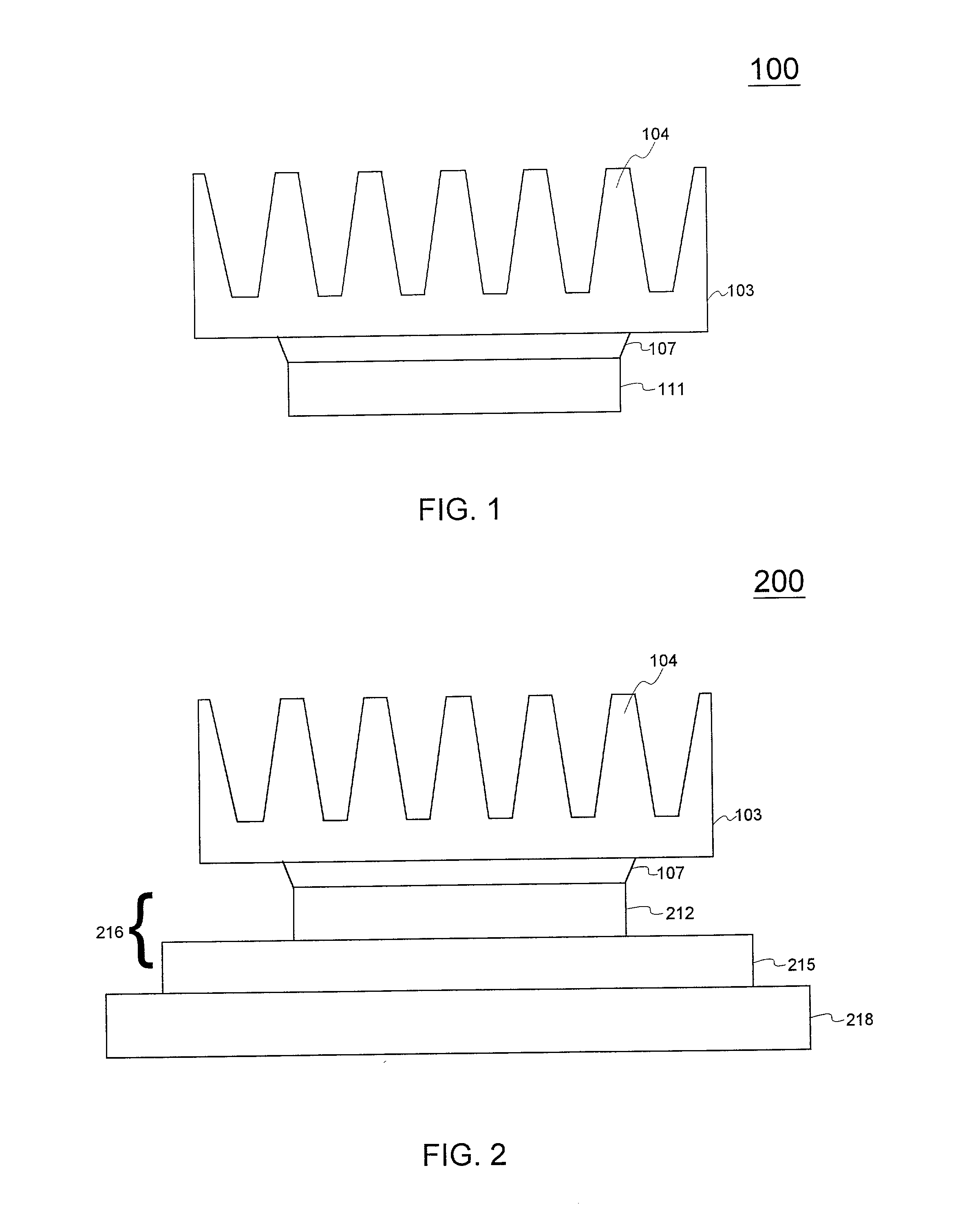
[0027] Referring now to FIGS. 1 through 3, various systems according to the present invention and products made in accordance with methods described herein, will now be described in detail. Accordingly, FIG. 1 is a side view schematically illustrating the bond between a heat-producing device 111 and a heat-absorbing apparatus 103 in exemplary embodiment 100 of the present invention. In the exemplary embodiment illustrated, heat-absorbing apparatus 103 is a heat sink, having fins 104. In the embodiment wherein heat-absorbing apparatus 103 is a heat sink, heat-absorbing apparatus 103 may be a heat sink as described above or as known in the art, and may have a different shape than shown, including being a structural component or enclosure. Heat-absorbing apparatus 103 may be another type heat-absorbing apparatus, including those described above. Heat-producing device 111 may be a mechanical or electrical device as described above, such as a computer chip or CPU. The thermal bond betwee...

exemplary embodiment 200

[0029] FIG. 2 is a side view schematically illustrating the bond between a heat-absorbing apparatus 103 and a CPU 216 mounted on a circuit board such as a printed circuit board (PCB) 218 in exemplary embodiment 200 of the present invention. As described above with reference to FIG. 1, the heat-absorbing apparatus 103 illustrated is shown as a heat sink with fins 104, but may be another type heat sink including those described above or known in the art, or may be another type heat-absorbing apparatus. CPU 216 may be a flip-chip CPU as shown, and may be a flip-chip pin grid array (FC-PGA) or a ball grid array (BGA). Thermal solutions may be attached directly to the back of the processor core package without the use of a thermal paste or heat spreader. CPU 216 may be comprised of CPU silicon die 212 and die carrier 215 as shown, which may be attached in ways known in the art. Silicon die 212 may be flipped (top down) on a substrate containing the solder balls or pins, and directly sold...

exemplary embodiment 300

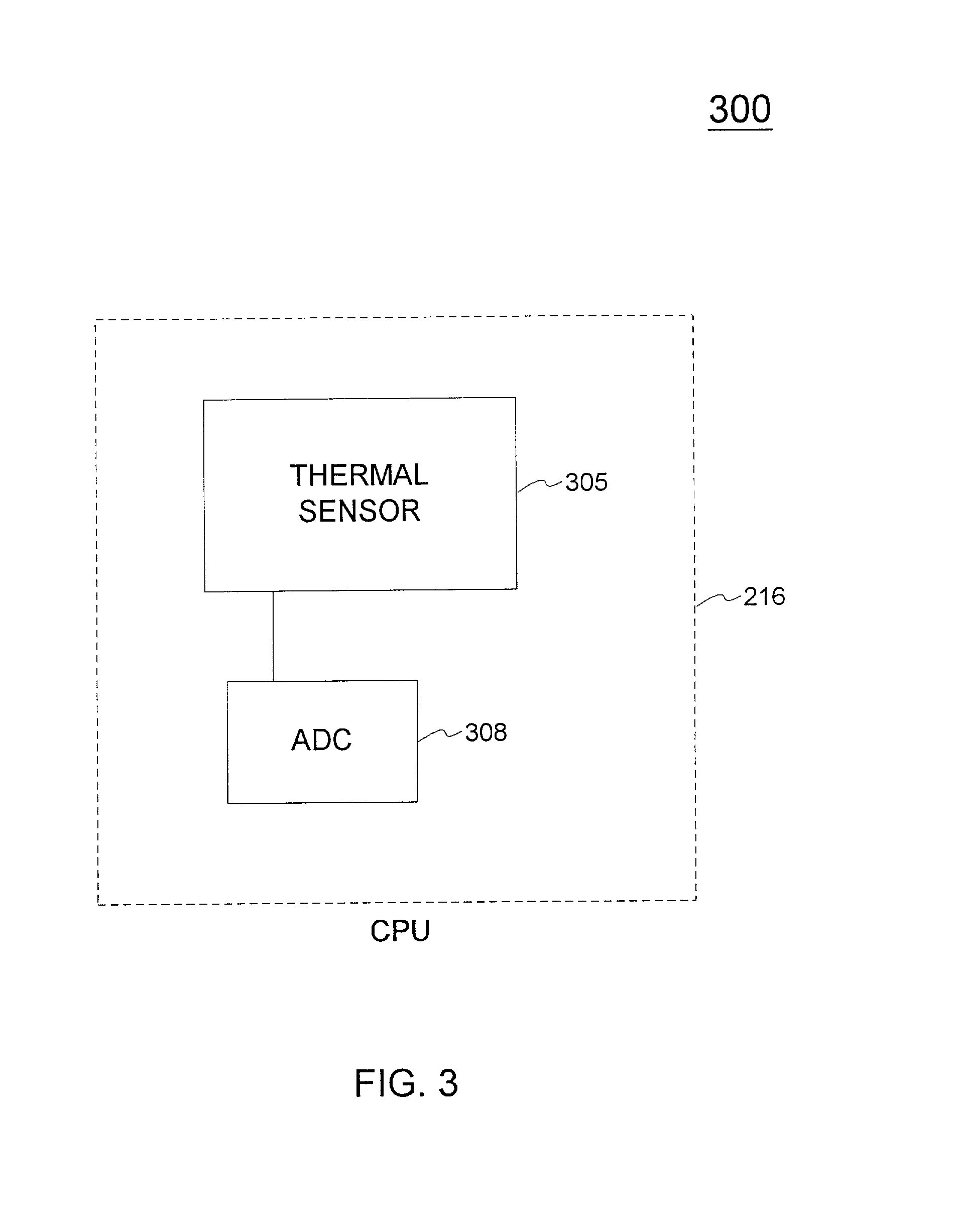
[0030] A thermal sensor is typically located integral with, in contact with, or near, heat-producing device 111 or CPU 216. Accordingly, FIG. 3 is a block diagram illustrating a thermal sensor 305 on a CPU 216 in exemplary embodiment 300 of one aspect of the present invention. Although in the example shown, CPU 216 is a CPU, it may be another heat-producing device, e.g. heat-producing device 111 in FIG. 1. Thermal sensor 305 may be a thermal diode, a thermocouple, a thermistor, a resistance temperature detector (RTD), and infrared temperature measuring device, a thermometer, or any other device or system suitable for measuring temperature. CPU 216 may also have an analog to digital converter (ADC) 308 connected to thermal sensor 305 that may be read by CPU 216 and used to provide temperature readings, e.g. with a resolution of 1.degree. C. and accuracy of + / -2.degree. C. Although thermal sensor 305 and ADC 308 are shown being on-board or integral with CPU 216, either or both may be ...


PUM

PropertyMeasurementUnit
timeaaaaaaaaaa
timeaaaaaaaaaa
thicknessaaaaaaaaaa

Abstract

A system and method for evaluating the thermal bond between a heat-producing device and a heat-absorbing apparatus. The heat-producing device may be a CPU, such as an INTEL PENTIUM microprocessor, and the heat-absorbing apparatus may be a heat sink. The two may be joined with a heat-conducting substance such as thermal grease or adhesive. In one exemplary embodiment, the heat-producing device is operated at a first power level, a first temperature measurement is then taken, the device is operated at a second power level, and then a second temperature measurement is then taken. The thermal resistance is then calculated, which may involve subtracting the second temperature from the first, and may involve dividing by the power level. The first power level may be full power, and the second power level may be near zero. The first temperature may be measured when equilibrium temperatures have been reached, and the second temperature may be measured a predetermined amount of time after the second power level is initiated, which may be just enough time for the temperatures of the CPU and the heat sink to equalize. The CPU may perform the calculations, and the temperature may be measured with an on-board thermal sensor which may be a thermal diode.

Description

[0001] 1. Field of the Invention[0002] This invention relates generally to systems and methods for evaluating thermal bonds.[0003] 2. Description of the Related Art[0004] Many mechanical and electrical devices generate heat internally which must be dissipated to the environment to keep the devices within a range of desired operating temperatures. Such heat-producing devices may include engines, bearings, motors, power supplies, transformers, amplifiers, control modules, and computer chips and components including graphics controllers, network interfaces, and central processing units (CPUs). In some applications it is desirable to transfer heat from a heat-producing device to a heat-absorbing apparatus so that the heat may be used for useful purposes. These useful purposes may include generating electricity, providing heat for industrial processes, heating water, heating air (e.g. to heat the occupied space in buildings), or preventing freezing. Heat-absorbing apparatuses may compris...

Claims


Application Information

Patent Timeline
Patent Type & Authority Applications(United States)
IPC IPC(8): G01N25/18G01N25/72
CPCG01N25/72G01N25/18
Inventor SCHONATH, PETERWELLER, STEVEN A.
Owner SBS TECH
Why Eureka
Try Eureka