Nutating pump, control system and method of control thereof

a technology of control system and nut, which is applied in the direction of piston pump, positive displacement liquid engine, instruments, etc., can solve the problems of inaccurate fluid dispensing and reduce the possibility of splashing, so as to increase the intake flow rate, increase the motor speed, and increase the speed

Inactive Publication Date: 2002-12-26
FLUID MANAGEMENT LLC
View PDF3 Cites 16 Cited by
  • Summary
  • Abstract
  • Description
  • Claims
  • Application Information

AI Technical Summary

Benefits of technology

0018] In addition to breaking down a piston rotation into a plurality of steps, the control system also acts to reduce the motor speed during those steps of the profile where the dispense rate is highest (i.e. the peak of the sinusoidal dispense profile) which reduces the possibility of splashing and therefore an inaccurate dispense of fluid. In an embodiment, the control system may also increase the motor speed during the intake portion of the profile. The speed can be increased during the intake in a variety of ways. One embodiment would involve increasing the motor speed during the beginning and end portions of the intake to increase the intake flow rate at the beginning and end portions of the intake without increasing the peak intake flow rate.
0019] Another embodiment involves a uniform increase of motor speed during the intake portion of the cycle which would, of course, increase the peak intake flow rate. An advantage of increasing motor speed during the intake portion of the profile would be to make up for lost time which results from reducing the peak dispense rate during the dispense portion of the profile. Of course, other embodiments would include reducing motor speed and peak dispense rate during the dispense portion of the profile without modifying the intake portion of the profile.
0020] The nutating pump of the present invention can be adjustable. For example, the angle between the axis of the nutating pump piston and the axis of the stepper motor shaft can be adjusted by an actuator. The computer control system sends signals to the actuator to operate the actuator which positions the nutating pump piston at a desired angle. The automated nutating pump angle adjustment effectively adjusts the pump fluid output through computer control.

Problems solved by technology

In addition to breaking down a piston rotation into a plurality of steps, the control system also acts to reduce the motor speed during those steps of the profile where the dispense rate is highest (i.e. the peak of the sinusoidal dispense profile) which reduces the possibility of splashing and therefore an inaccurate dispense of fluid.

Method used


Image

  • Nutating pump, control system and method of control thereof
  • Nutating pump, control system and method of control thereof
  • Nutating pump, control system and method of control thereof

Examples


Embodiment Construction

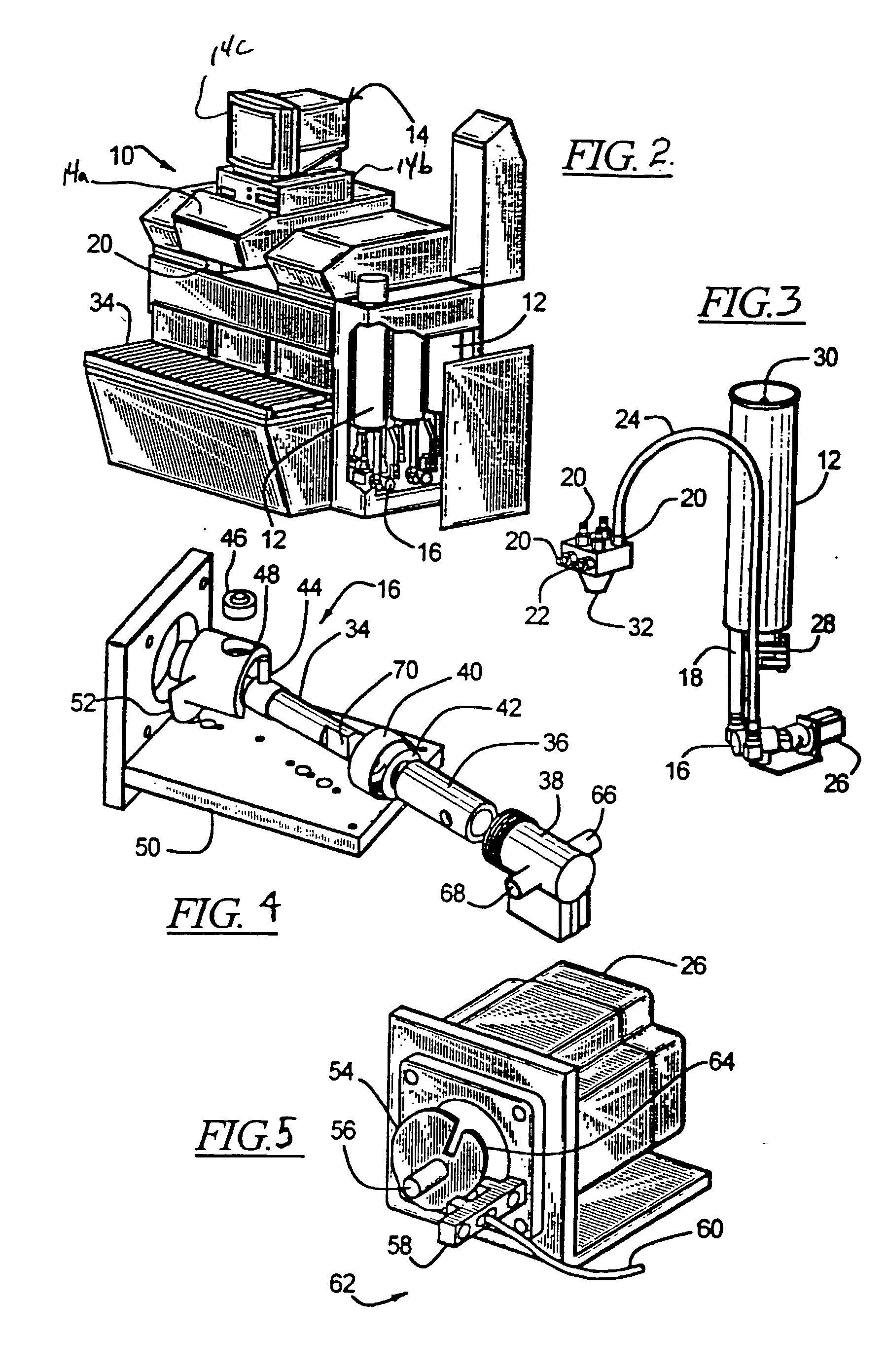
[0058] A fluid dispense system 10 according to the disclosure is shown in FIG. 2. The fluid dispense system 10 dispenses a variety of paint colorant colorants from several colorant canisters 12 which hold bulk colorants. Of course the dispense system 10 is clearly applicable to fluid dispense systems other than paint colorant dispense systems. The fluid dispense system 10 has a computer control system 14 which stores the paint color formulas and operatively controls the fluid dispense system 10 to dispense the correct colorants and amounts of the colorants into a base paint. Once the proper colorants have been dispensed into the base paint, the coloranted paint is thoroughly mixed to produce a mixed paint of the desired color.

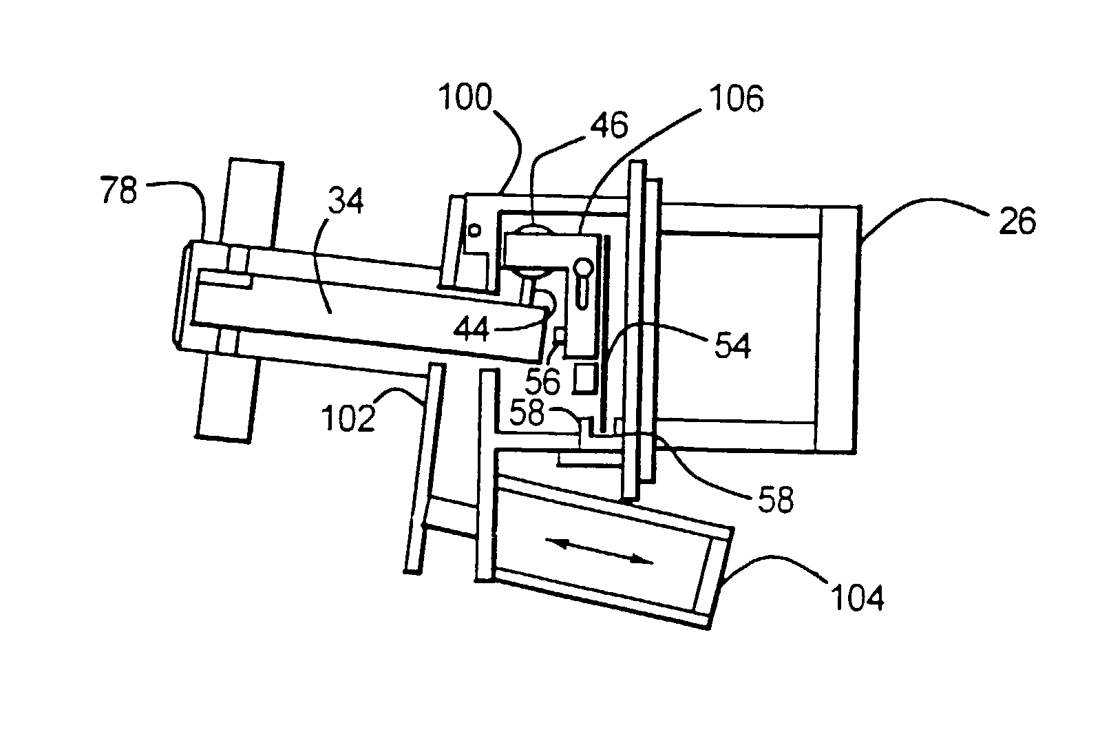
[0059] Referring to FIGS. 2 and 3, each colorant canister 12 is fluidly connected to an inlet to a fluid pump 16 by a tube 18. The embodiment shown in FIGS. 2 and 3 includes a nutating pump as the fluid pump 16; however, other fluid pumps are contemplated by th...


PUM


Abstract

A fluid dispense system having a computer control system that operatively controls a stepper motor driving a pump. The stepper motor actuates the pump piston through partial revolutions. The computer control system determines the number of stepper motor steps required to pump a desired amount of fluid by the pump by rotating the piston through segments which are less than a full revolution. Further, the controller varies the speed of the stepper motor to avoid splashing of the dispense fluid and motor stalling.

Description

[0001] This application is a continuation-in-part of U.S. patent application Ser. No. 09 / 920,976 filed on Aug. 2, 2001, which is a divisional application of U.S. patent application Ser. No. 09 / 665,695 filed on Sep. 20, 2000, now U.S. Pat. No. 6,398,513 issued on Jun. 4, 2002.[0002] 1. Technical Field[0003] An improved nutating pump is disclosed as well as control systems for nutating pumps and methods of controlling dispense rates of nutating pumps so as to prevent, on one hand, splashing, and, on the other hand, motor stalling. The nutating pumps, control systems and methods disclosed herein are applicable to the field of paint colorant dispensers but have numerous other applications as well.[0004] 2. Description of the Related Art[0005] Paints are made in a vast number of different colors and shades of colors. Each specific paint color has a specific formula of components to provide the desired color. A paint formula generally includes a relatively large amount of a base and small...

Claims


Application Information

Patent Timeline
Patent Type & Authority Applications(United States)
IPC IPC(8): B01F13/10B01F15/04G01F11/02G01F11/20G01F11/22
CPCB01F13/1055B01F15/0243B01F15/0454G01F11/22G01F11/021G01F11/029G01F11/20F04B49/065B01F33/84B01F35/7176B01F35/882
Inventor HOGAN, TIMAMSLER, THOMAS J.CLEVELAND, JAMES R.
Owner FLUID MANAGEMENT LLC
Why Eureka
Try Eureka