Driving method for liquid crystal device

a liquid crystal device and driving method technology, applied in the direction of instruments, static indicating devices, etc., can solve the problems of poor motion picture quality, unsuitable motion picture display, and the inability to improve motion picture quality only by a short response tim

Inactive Publication Date: 2003-01-09
CANON KK
View PDF0 Cites 13 Cited by
  • Summary
  • Abstract
  • Description
  • Claims
  • Application Information

AI Technical Summary

Benefits of technology

[0013] Thus, in the present invention, the total period of the preceding at least one sub-frame period is shortened and an intermediate state between the display and non-display states is displayed during the preceding sub-frame period(s) to improve the motion picture quality while suppressing a lowering in contrast, and the final sub-frame period is made longer to suppress the adverse effect accompanying the signal transmission delay along the panel electrodes.

Problems solved by technology

Among these, a liquid crystal material classified under a nematic liquid crystal has a long response time of 50 to several hundred msec, and the liquid crystal response is not completed in one frame period (16.7 msec, 60 Hz), so that a picture flow is caused in the case of a motion picture display to result in a poor motion picture quality, thus being unsuitable for motion picture display.
In recent years, however, it has been clarified that motion picture quality cannot be improved only by a short response time.
For example, it has been reported that a continuous lighting-type display device (hold-type display device), such as a liquid crystal device, provides an inferior motion picture quality in principle compared with a pulse lighting-type display device (non-hold-type display device), such as a CRT (cathode ray tube), in "Shingaku Giho EID 96-4 (1996), p.
However, of the above-mentioned display methods, the method of adopting a partially non-display period is accompanied with a difficulty of resulting in an effectively dark display due to a lowering in time-integrated luminance especially in the case where the non-display period is increased.
On the other hand, the method of relying on a higher frame display speed is liable to suffer from a signal transmission delay along panel electrodes and a display irregularity over a panel due to an increased drive frequency.
If .alpha. / .beta.is close to 1, the signal transmission delay can be problematic.
If .beta. is too short, it becomes difficult to improve the sharpness of motion picture display.

Method used


Image

  • Driving method for liquid crystal device
  • Driving method for liquid crystal device
  • Driving method for liquid crystal device

Examples


Embodiment Construction

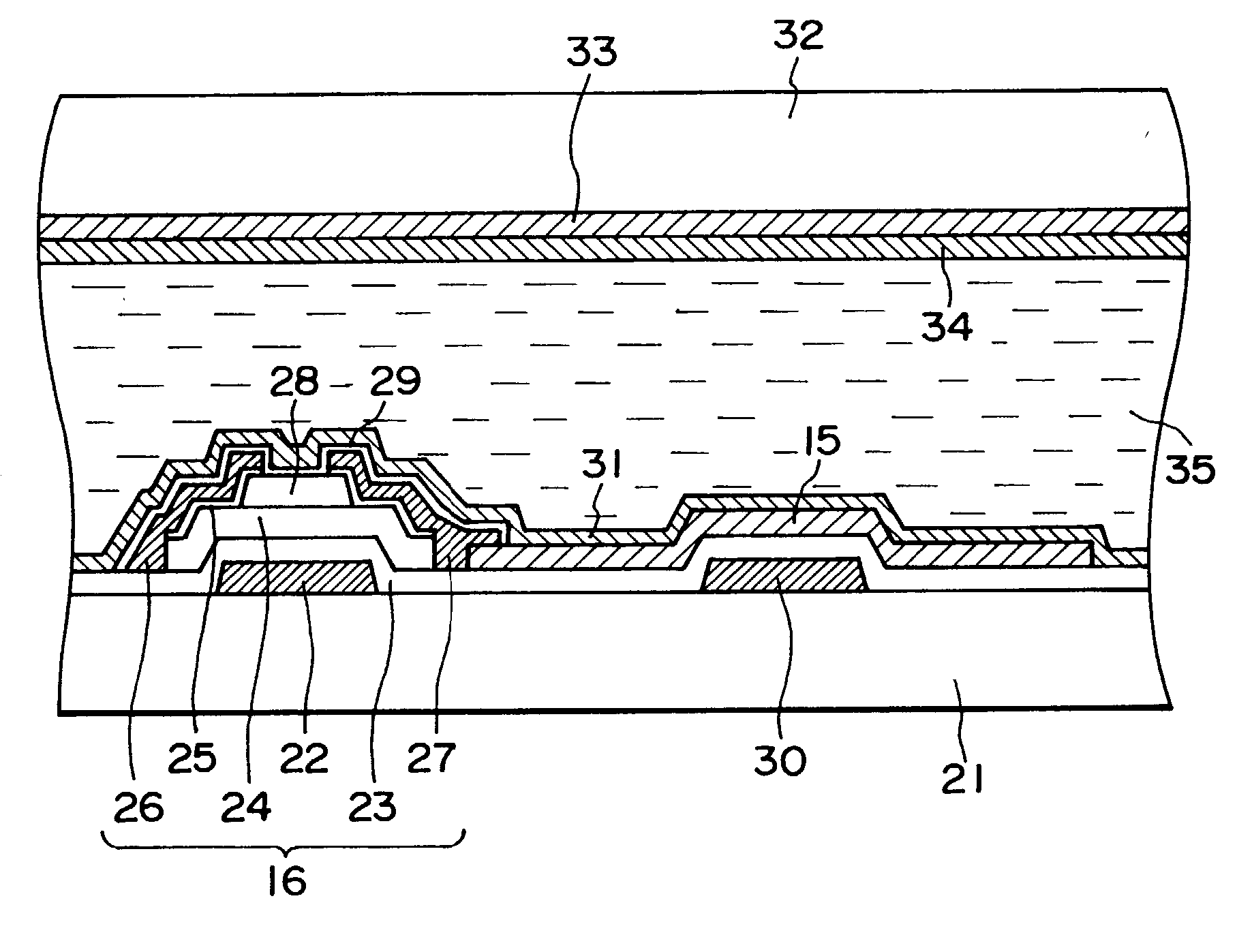
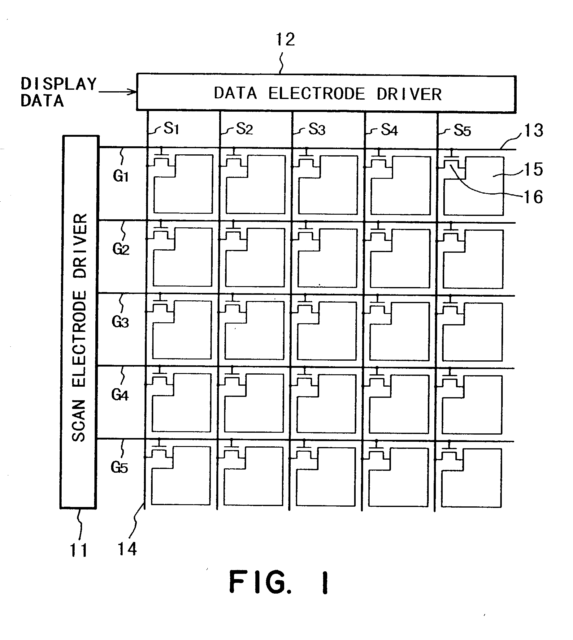
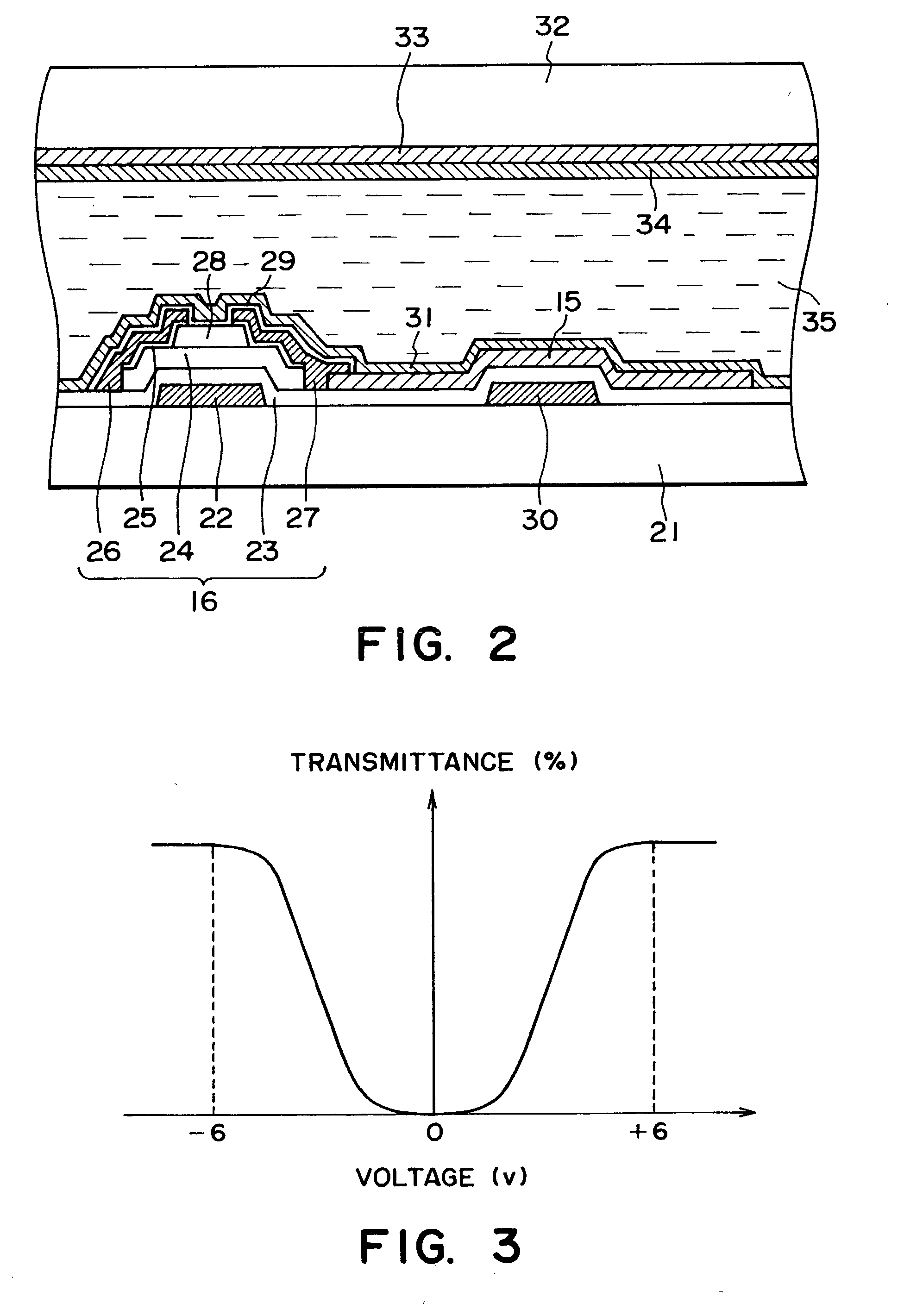
[0055] A liquid crystal device (panel) having an organization shown in FIGS. 1 and 2 and showing a V-character-shaped responsiveness shown in FIG. 3 was prepared and driven according to the driving methods illustrated in FIGS. 4, 10 and 11 respectively.

[0056] The liquid crystal device included 120.times.160 pixels and a TAFLC showing a spontaneous polarization of 150.times.10.sup.-9 C / cm.sup.2 at 30.degree.C., a tilt angle of 30 deg. from the rubbing direction and a dielectric constant of 5. Each pixel had an effective display area (opposing area of a pixel electrode and a common electrode) of 2.0.times.10.sup.-8 m.sup.2, a retention capacitance of 0.25 pF and a TFT having an on-resistance of 10 M.ohm.

[0057] In the driving method of FIG. 4, the parameters were set as follows:

[0058] F1=F2=. . . =16.8 msec, D1=4.8 msec,

[0059] D2=12 msec, H1=40 .mu.sec, H2=100 .mu.sec,

[0060] Vc=0 volt, Vg=25 volts, Vcs=10 volts,

[0061] Vs1=16 volts, Vs2=4 volts.

[0062] It was confirmed that a motion pict...


PUM

PropertyMeasurementUnit
frequencyaaaaaaaaaa
frequencyaaaaaaaaaa
transmittanceaaaaaaaaaa

Abstract

An active matrix-type liquid crystal panel is driven for a motion picture display in a succession of frame periods to provide an improved motion picture quality without causing a lowering in luminance or contrast, or a display irregularity over the panel due to a signal transmission delay along the panel electrodes. In the driving method, each frame period is divided into a plurality of sub-frame periods including at least one preceding sub-frame period and a final sub-frame period so that said at least one preceding sub-frame period provides a total period which is shorter than the final sub-frame period; the active elements along the rows of pixels are sequentially selected row by row at respective selection periods in each sub-frame period; and the liquid crystal at each pixel is supplied with a voltage in a selection period of each preceding sub-frame period which is lower than a voltage applied to the liquid crystal at the pixel in the final sub-final period.

Description

FIELD OF THE INVENTION AND RELATED ART[0001] The present invention relates to a driving method for a liquid crystal device for use as a light valve in a flat panel display, a projection display, a printer, etc.[0002] Various liquid crystal materials have been used in liquid crystal devices, such as nematic liquid crystals, smectic liquid crystals, polymer dispersion-type liquid crystals. Among these, a liquid crystal material classified under a nematic liquid crystal has a long response time of 50 to several hundred msec, and the liquid crystal response is not completed in one frame period (16.7 msec, 60 Hz), so that a picture flow is caused in the case of a motion picture display to result in a poor motion picture quality, thus being unsuitable for motion picture display.[0003] On the other hand, a chiral smectic liquid crystal having a spontaneous polarization has a shorter response time which is nearly one thousandth of that of a nematic liquid crystal, thus allowing a response i...

Claims


Application Information

Patent Timeline
Patent Type & Authority Applications(United States)
IPC IPC(8): G09G3/20G02F1/133G09G3/36
CPCG09G3/2022G09G3/2081G09G3/3648G09G2320/0261G09G2320/0266G09G2340/16G09G3/36
Inventor IBA, JUN
Owner CANON KK
Why Eureka
Try Eureka