Process for applying a heat shielding coating system on a metallic substrate
a coating system and heat shielding technology, applied in the direction of efficient propulsion technologies, machines/engines, transportation and packaging, etc., can solve the problems of high manufacturing cost, inability to expand the capacity of particular methods to all layers, and high investment required for electron beam guns
Active Publication Date: 2003-01-09
SULZER METRO AG
View PDF2 Cites 15 Cited by
- Summary
- Abstract
- Description
- Claims
- Application Information
AI Technical Summary
Problems solved by technology
It is understood that all these different application methods require the provision of a huge amount of available equipment for the different technologies, resulting in partially high manufacturing costs.
A particular disadvantage in connection with the EB-PVD method is the extremely high investment required for the electron beam gun, for an apparatus to provide a high-vacuum, for the high-vacuum chamber and for the partial pressure control apparatus.
Moreover, the capacities of the particular methods cannot be expanded to all layers.
By means of the EB-PVD method, for example, the areas of a substrate that are not directly visible during the coating operation cannot be coated at all or only insufficiently.
The more multifarious the choice of the different layers is made, the more complex the variety of the coating technologies will get.
Method used
View moreImage
Smart ImageViewing Examples
Examples
example 2
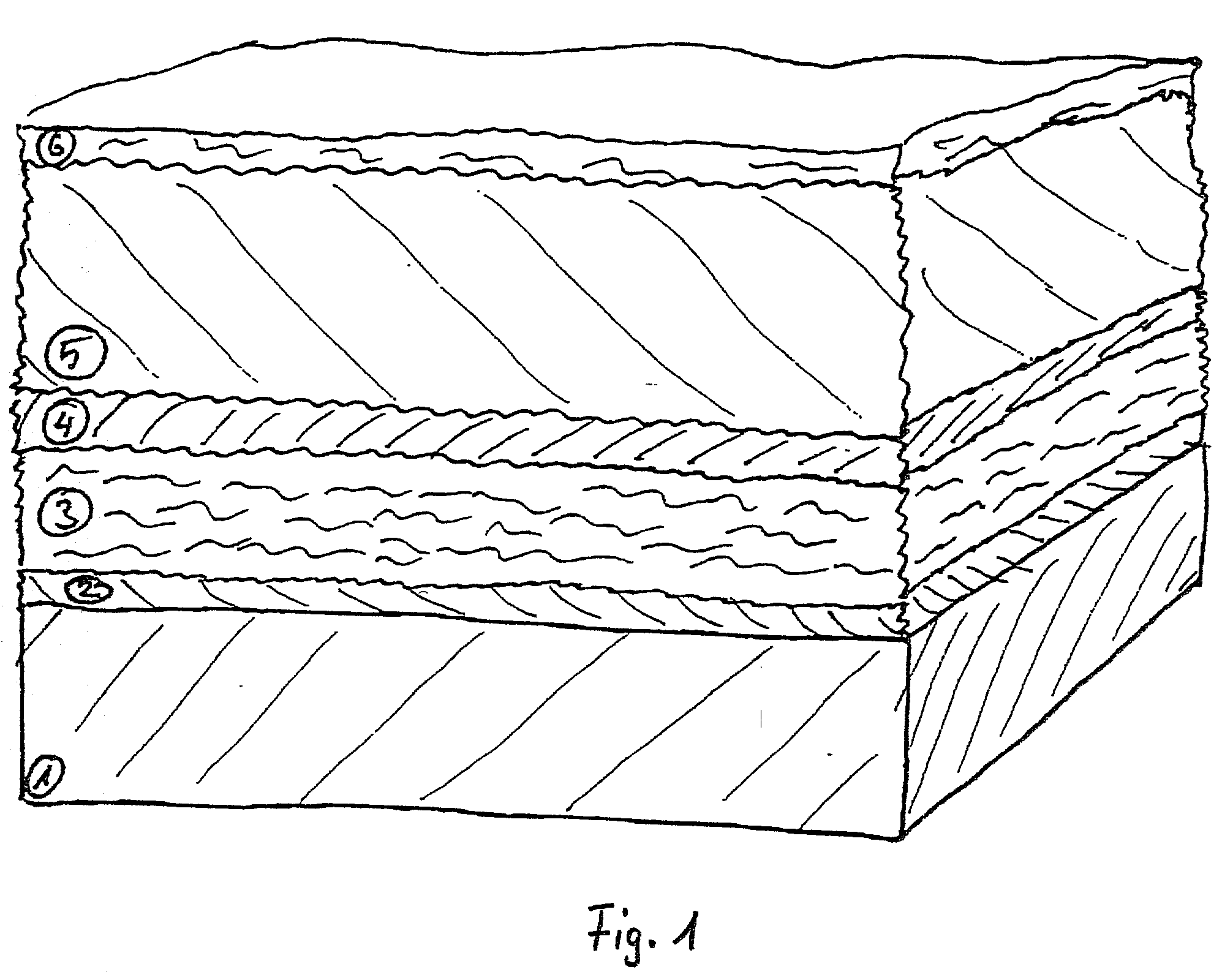
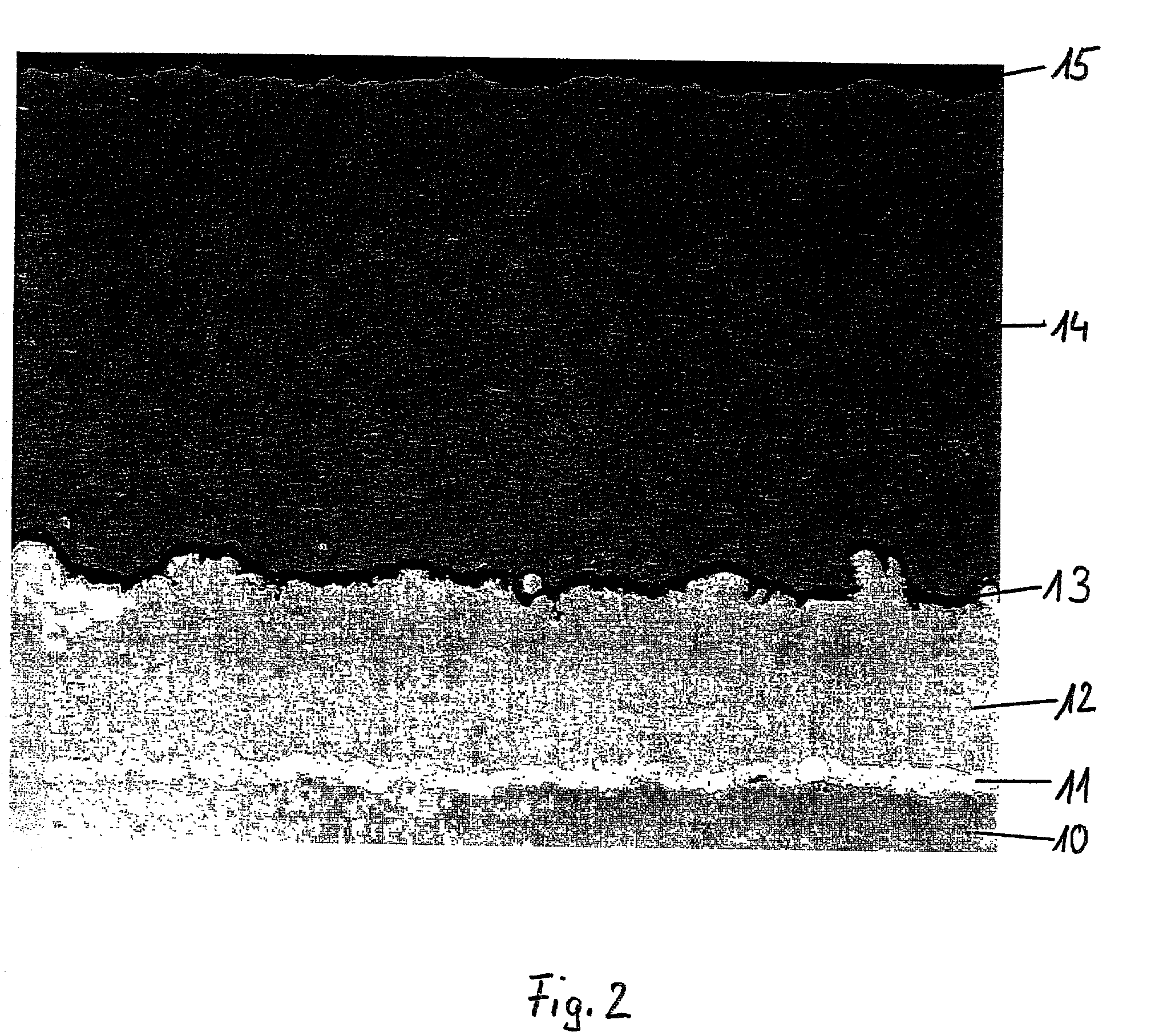
[0037] Following the process described in Example 1 herein above, the layer sequence illustrated in FIG. 2 has been manufactured. The parameters are as follows:
Login to View More PUM
| Property | Measurement | Unit |
|---|---|---|
| thickness | aaaaa | aaaaa |
| thickness | aaaaa | aaaaa |
| thickness | aaaaa | aaaaa |
Abstract
The invention provides a process for applying a heat shielding coating system on a metallic substrate. The coating system comprises at least three individual layers selected from the group of barrier layer, hot gas corrosion protection layer, protection layer, heat barrier layer, and smoothing layer. The coating system is applied to the metallic substrate by low pressure plasma spraying in a single operation cycle. This process enables the layers to be applied in an arbitrary sequence. The process is preferably used in applying a coating system to a turbine blade, particularly a stator or a rotor blade of a stationary gas turbine or of an aircraft engine, or to another component in a stationary or aircraft turbine that is subjected to hot gas.
Description
[0001] The most significant progress, as far as an increase in performance of machines like turbines are concerned, can be realized by increasing the process temperature. However, such increase in process temperature can result in the fact that metallic components of the machine are stressed beyond the limits of their safe operating area such that these components will not endure an operation under these conditions for a long time without damage or at least alteration of their properties.[0002] It is well known in the prior art to make use of coatings applied to such metallic components in order to protect them from such critical operating conditions. For example, ceramic heat shield coats are used to decrease the heat conductivity between process chamber and machine component, or metallic coats to increase the hot gas corrosion resistance of the surface of such metallic machine components. For many years, such coats are also applied by a thermal coating process; nowadays, they are ...
Claims
Login to View More Application Information
Patent Timeline
 Patent Type & Authority Applications(United States)
IPC IPC(8): F01D5/28C23C4/02C23C4/137F02C7/00
CPCC23C4/02C23C4/128Y10T428/12944Y10T428/12611Y10T428/12861Y02T50/67C23C4/137Y02T50/60
Inventor LOCH, MICHAELBARBEZAT, GERARD
Owner SULZER METRO AG
Features
- R&D
- Intellectual Property
- Life Sciences
- Materials
- Tech Scout
- Unparalleled Data Quality
- Higher Quality Content
- 60% Fewer Hallucinations
Learn More Browse by: Latest US Patents, China's latest patents, Technical Efficacy Thesaurus, Application Domain, Technology Topic, Popular Technical Reports.
© 2025 PatSnap. All rights reserved.Legal|Privacy policy|Modern Slavery Act Transparency Statement|Sitemap|About US| Contact US: help@patsnap.com


