
Acquisition and replay systems for direct-to-digital holography and holovision

a technology of acquisition and replay system, applied in the field of holography, can solve the problems of inability to reduce, delay in film processing, slow analog method, etc., and achieve the effect of preventing the use of holography and its variants in many situations, and reducing the cost of holography

Inactive Publication Date: 2003-01-23
UT BATTELLE LLC
View PDF3 Cites 33 Cited by
  • Summary
  • Abstract
  • Description
  • Claims
  • Application Information

AI Technical Summary

Benefits of technology

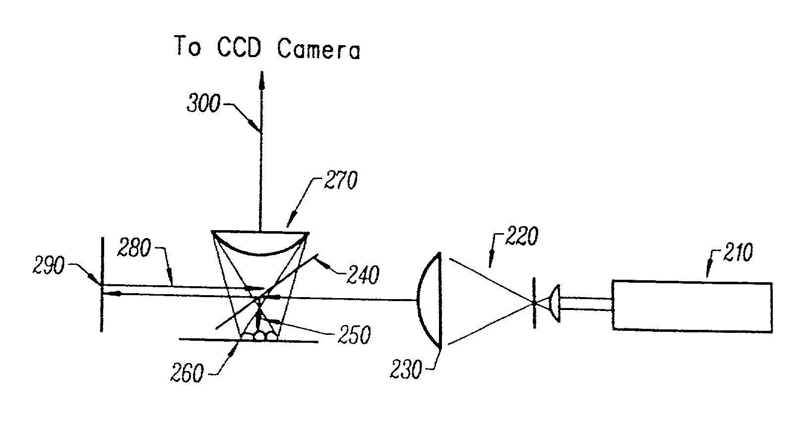
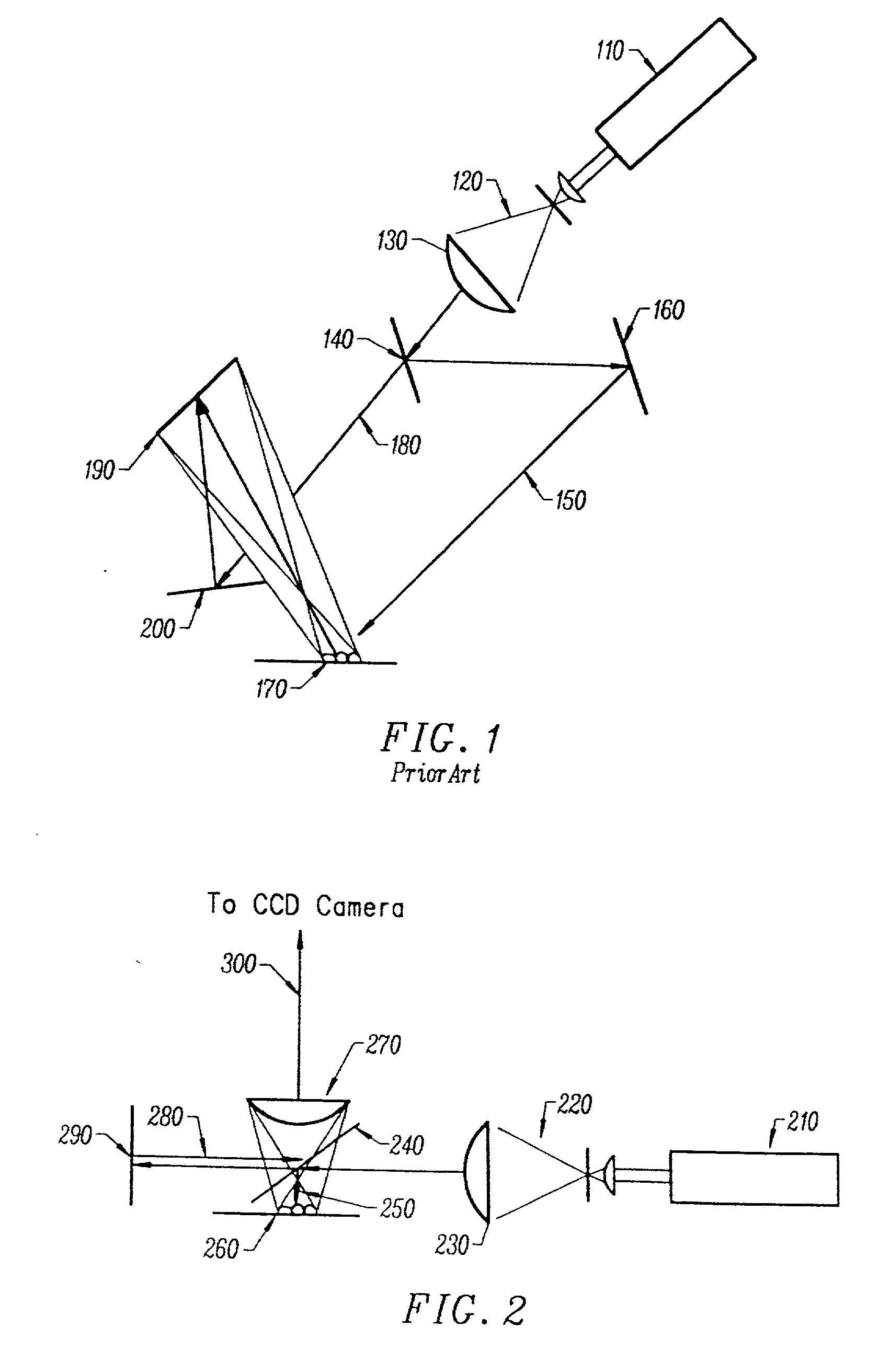
[0131] A direct-to-digital hologram system, representing an embodiment of the invention is cost effective and advantageous for at least the following reasons. The combination of high resolution CCD, and optical techniques that reduce the density of the interference pattern (fringes) to a density that the CCD can record, combined with the Fourier transform techniques developed for interferometry and by Dr.Voelkl for electron holography, allow the electronic recording and replay of holograms.

Problems solved by technology

These analog methods are slow, cumbersome, and expensive.
(.sup.4) There is also no way to reduce them to electronic signals that can be transmitted and replayed at another location.
Worse still, the time delay involved in processing the film prevents the use of holography and its variants in many situations.
Even if the expense of the classical holographic system itself was tolerable, the time delay and low throughput caused by the necessity of processing the film, introduces expenses associated with the delay that are absolutely intolerable (e.g., a tire manufacturer cannot wait 45 minutes, or even two minutes, to know that a particular tire has a flaw in it).

Method used


Image

  • Acquisition and replay systems for direct-to-digital holography and holovision
  • Acquisition and replay systems for direct-to-digital holography and holovision
  • Acquisition and replay systems for direct-to-digital holography and holovision

Examples


example

[0057] A specific embodiment of the present invention will now be further described by the following, nonlimiting example which will serve to illustrate in some detail various features of significance. The example is intended merely to facilitate an understanding of ways in which the present invention may be practiced and to further enable those of skill in the art to practice the present invention. Accordingly, the example should not be construed as limiting the scope of the present invention.

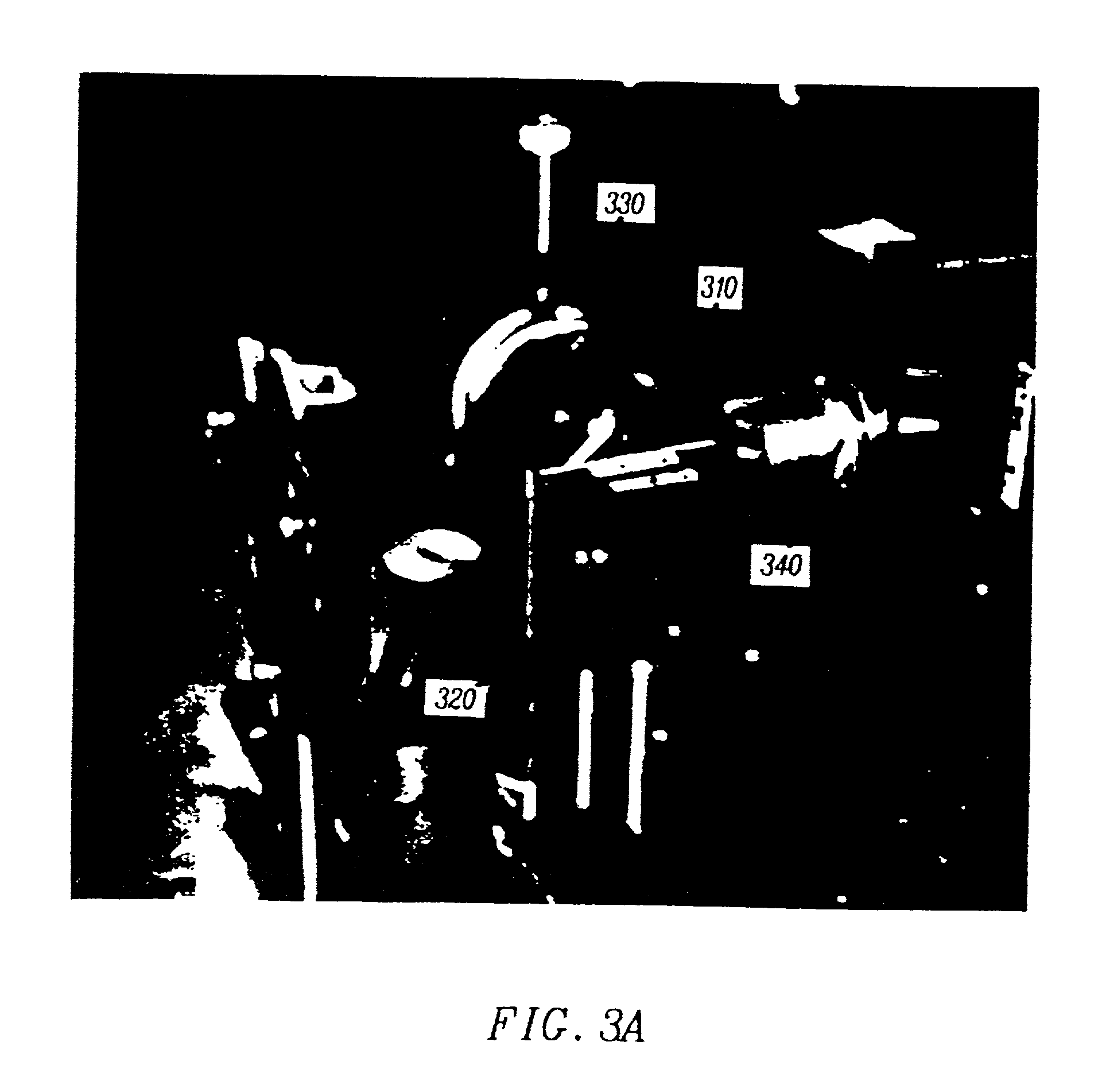
[0058] FIG. 3A is a perspective view of an exemplary "Michelson" geometry for direct-to-digital holography is shown. Laser light is provided to a beamsplitter 310. An object beam from the beamsplitter 310 travels to a semiconductor wafer mount 320 and then to a focusing lens 330. Meanwhile, a reference beam from the beamsplitter 310 travels to a reference beam mirror that is mounted on a piezoelectric reference beam mirror mount 340.

[0059] FIG. 3B is another perspective view of the exemplary r...


PUM


Abstract

Improvements to the acquisition and replay systems for direct-to-digital holography and holovision are described. A method of recording an off-axis hologram includes: splitting a laser beam into an object beam and a reference beam; reflecting the reference beam from a reference beam mirror; reflecting the object beam from an illumination beamsplitter; passing the object beam through an objective lens; reflecting the object beam from an object; focusing the reference beam and the object beam at a focal plane of a digital recorder to form an off-axis hologram; digitally recording the off-axis hologram; and transforming the off-axis hologram in accordance with a Fourier transform to obtain a set of results. A method of writing an off-axis hologram includes: passing a laser beam through a spatial light modulator; and focusing the laser beam at a focal plane of a photorefractive crystal to impose a holographic diffraction grating pattern on the photorefractive crystal. A method of replaying an off-axis hologram includes: illuminating a photorefractive crystal having a holographic diffraction grating with a replay beam.

Description

[0001] This application is a continuation-in-part under 35 U.S.C. .sctn. 120 of copending U.S. Ser. No. 08 / 873,252, filed Jun. 11, 1997, now pending, the entire contents of which are hereby incorporated herein by reference as if fully set forth herein.[0003] 1. Field of the Invention[0004] The present invention relates generally to the field of holography. More particularly, the present invention relates to a direct-to-digital hologram acquisition and replay system (i.e., no film, no plates). In a preferred implementation of the present invention, the hologram acquisition is based on a charge coupled device (CCD) camera. The present invention thus relates to a holographic system.[0005] 2. Discussion of the Related Art[0006] Traditional methods of holography have used film or holographic plates (glass plates with a photographic emulsion optimized for holography) to record the hologram.(.sup.1) Replay has only been possible using lasers (or in some cases white light) and the original ...

Claims


Application Information

Patent Timeline
IPC IPC(8): G03H1/02G03H1/04G01B9/021G03H1/08G03H1/22
CPCG01B9/021G03H1/02G03H1/0406G03H1/0443G03H1/0866G03H1/0891G03H1/22G03H1/2294G03H2001/0033G03H2001/005G03H2001/0066G03H2001/0088G03H2001/0456G03H2001/2263G03H2222/18G03H2226/11G03H1/2249G03H2210/30G03H1/04
Inventor THOMAS, CLARENCE E.HANSON, GREGORY R.
Owner UT BATTELLE LLC
Learn More