Color scannerless range imaging system using an electromechanical grating

a color scanner and electromechanical grating technology, applied in the field of three-dimensional image capture, can solve the problems of color information loss, added cost of two image capture devices, color information loss, etc., and achieve the effects of less expensive, less fragile, and lighter in weigh

Inactive Publication Date: 2003-01-30
MONUMENT PEAK VENTURES LLC
View PDF0 Cites 9 Cited by
  • Summary
  • Abstract
  • Description
  • Claims
  • Application Information

AI Technical Summary

Benefits of technology

0012] Consequently, an advantage of the invention is that it provides both an alternative to the intensifier and a simplified technique for capturing a color texture image as well as one or more phase images. A further advantage of the invention is that it eliminates the need for an expensive component, i.e., the intensifier, with a device that is significantly less expensive and less fragile. The electromechanical grating is also lighter in weight and more compact than a micro-channel plate, and uses a lower operating voltage. Moreover, the system is able to capture a color image in addition to the phase images without the sort of clever work-arounds shown in the prior art. The system is also able to operate in a continuous modulation mode or in a pulse mode.
0013] These and other aspects, objects, features and advantages of the present invention will be more clearly understood and appreciated from a review of the following detailed description of the preferred embodiments and appended claims, and by reference to the accompanying drawings.

Problems solved by technology

A drawback of methods using an image intensifier is that color information is lost.
Unfortunately for color applications, an image intensifier operates by converting photonic energy into a stream of electrons, amplifying the energy of the electrons and then converting the electrons back into photonic energy via a phosphor plate.
One consequence of this process is that color information is lost.
Besides the added expense of two image capture devices, there are additional drawbacks in the need to register the two image planes precisely, together with alignment of the optical paths.
Another difficulty is collating image pairs gathered by different sources.
This approach is described in detail in commonly assigned copending application Ser. No. 09 / 451,823, entitled "Method and Apparatus for a Color Scannerless Range Image System" and filed Nov. 30, 1999 in the names of Lawrence A. Ray, Louis R. Gabello and Kenneth J. Repich. The drawback of this approach is the need to switch lenses and the possible misregistration that might occur due to the physical exchange of lens elements.
There is an additional drawback in the time required to swap the two optical assemblies, and the effect that may have on the spatial coincidence of the images.
In addition to the loss of color information, and the consequent necessity to devise techniques as described above to overcome this drawback, the image intensifier is a costly part and, in addition, can be fragile.

Method used


Image

  • Color scannerless range imaging system using an electromechanical grating
  • Color scannerless range imaging system using an electromechanical grating
  • Color scannerless range imaging system using an electromechanical grating

Examples


Embodiment Construction

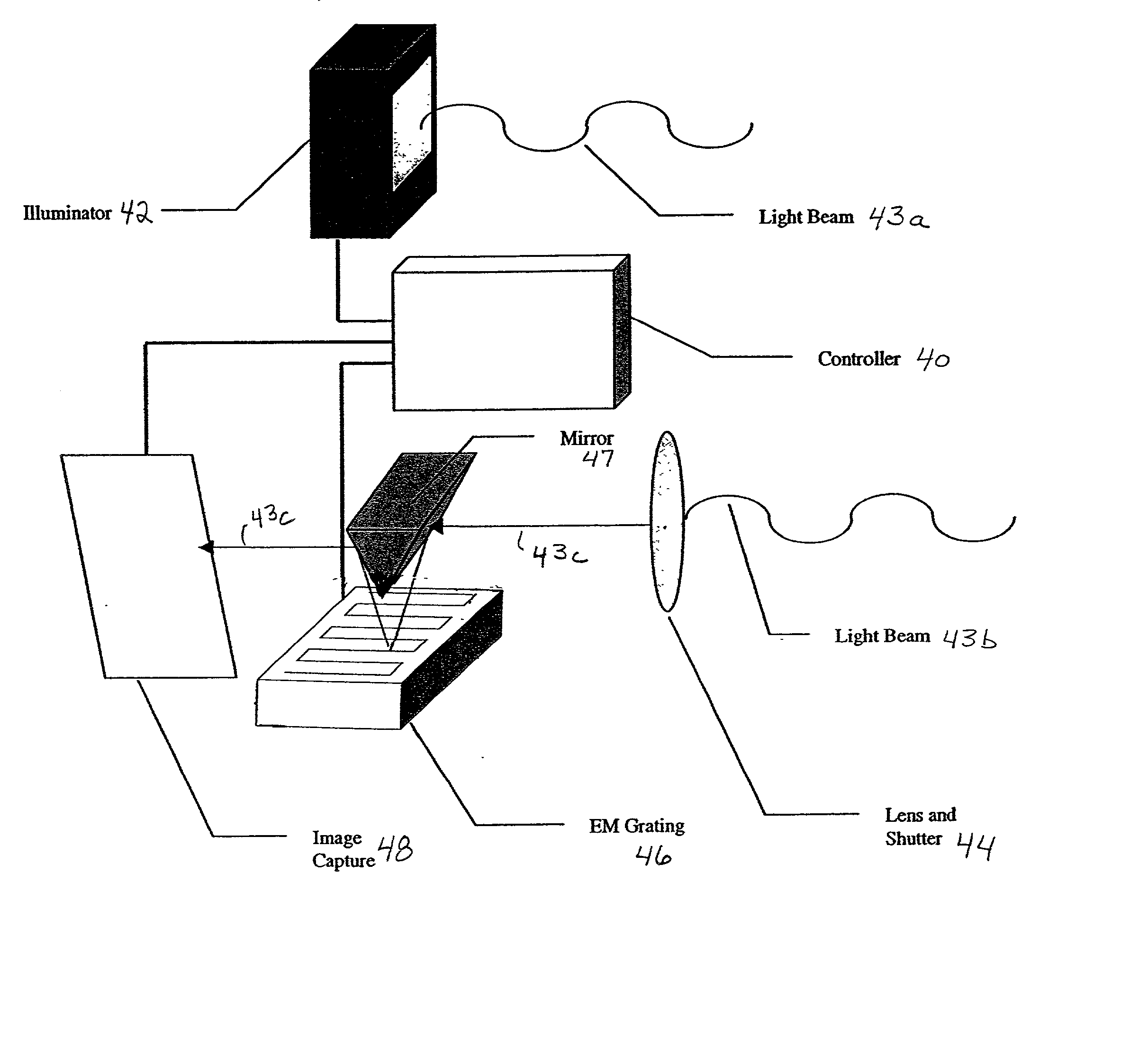
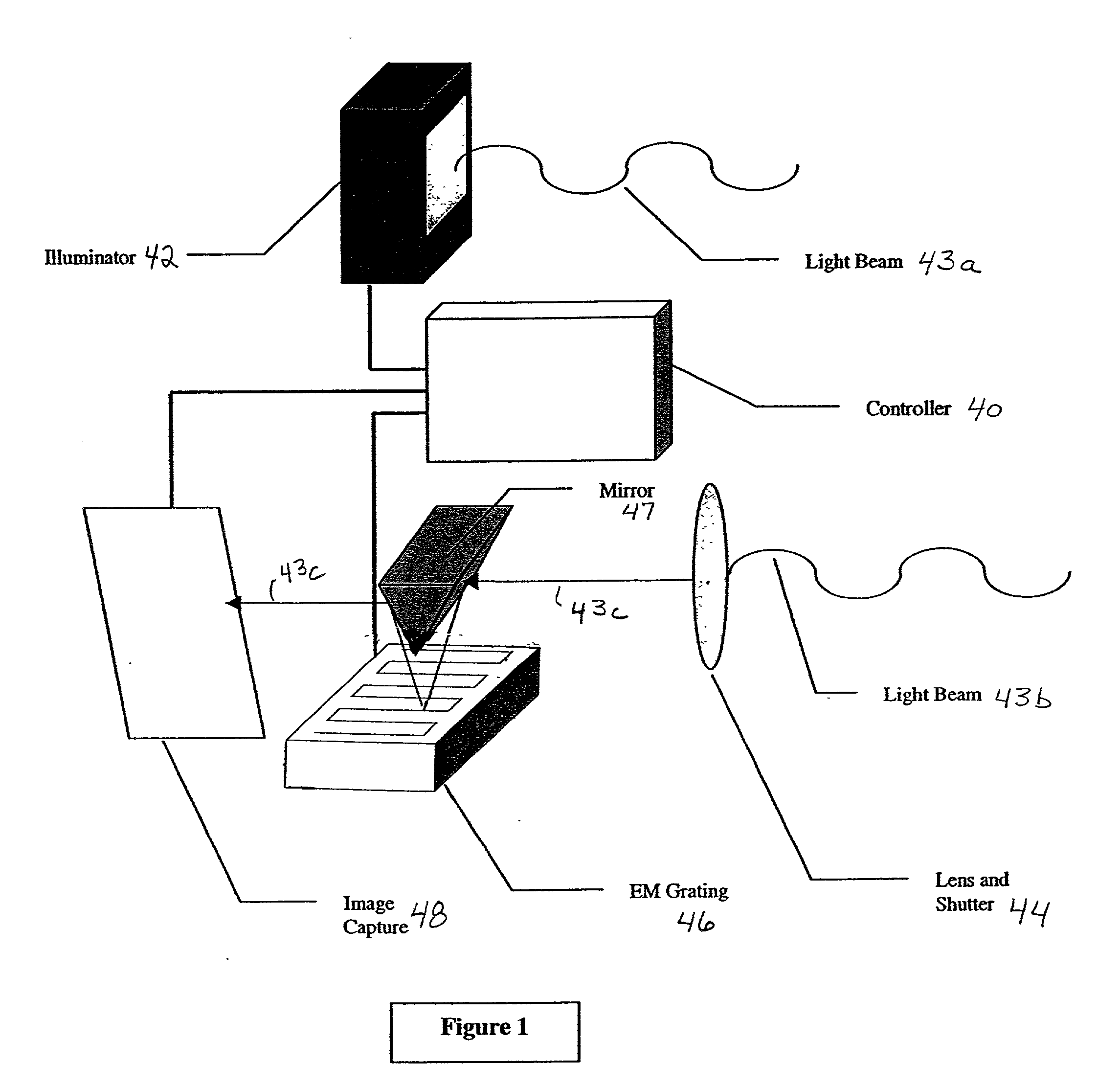
[0019] Because range imaging devices employing laser illuminators and capture devices including image intensifiers and electronic sensors are well known, the present description will be directed in particular to elements forming part of, or cooperating more directly with, apparatus in accordance with the present invention. Elements not specifically shown or described herein may be selected from those known in the art. Certain aspects of the embodiments to be described may be provided in software. Given the system as shown and described according to the invention in the following materials, software not specifically shown, described or suggested herein that is useful for implementation of the invention is conventional and within the ordinary skill in such arts.

[0020] It is helpful to first review the principles and techniques involved in scannerless range imaging, as known in the prior art. Accordingly, referring first to FIG. 6, a known scannerless range imaging system 10 is shown a...


PUM


Abstract

A scannerless range imaging system includes an illumination system and an electromechanical light modulator. The illumination system illuminates objects in the scene with modulated illumination of a predetermined modulation frequency, and the modulated illumination reflected from objects in the scene incorporates a phase delay corresponding to the distance of the objects from the range imaging system. The electromechanical light modulator, which is positioned in an optical path of the reflected illumination, operates at a reference frequency that corresponds to the predetermined modulation frequency and accordingly modulates the modulated illumination reflected from the object, thereby generating a phase image from the interference between the reference frequency and the reflected modulated illumination. The system further includes an optical system that deflects the reflected illumination to the electromechanical light modulator and redirects the phase image generated by the electromechanical light modulator to an image capture section. A color image may be captured by moving the optical system out of the optical path such that reflected illumination from the object will pass directly to the image capture section without contacting the electromechanical light modulator.

Description

FIELD OF THE INVENTION[0001] The present invention relates to the field of three-dimensional image capture and in particular to techniques for modulating the reflected light in order to extract phase images and for capturing a color texture image in conjunction with the phase image.BACKGROUND OF THE INVENTION[0002] Distance (or depth) information from a camera to objects in a scene can be obtained by using a scannerless range imaging system having a modulated illumination source and a modulated image receiver. In a method and apparatus described in U.S. Pat. No. 4,935,616 (and further described in the Sandia Lab News, vol. 46, No. 19, Sep. 16, 1994), a scannerless range imaging system uses either an amplitude-modulated high-power laser diode or an array of amplitude-modulated light emitting diodes (LEDs) to simultaneously illuminate a target area. Conventional optics confine the target beam and image the target onto a receiver, which includes an integrating detector array sensor hav...

Claims


Application Information

Patent Timeline
Patent Type & Authority Applications(United States)
IPC IPC(8): G01S17/89G02B26/00G01S17/36G02B5/18G02B7/28G02B7/40
CPCG01S17/36G01S17/89
Inventor BRAZAS, JOHN C.GABELLO, LOUIS R.KOWARZ, MAREKRAY, LAWRENCE A.REPICH, KENNETH J.
Owner MONUMENT PEAK VENTURES LLC
Why Eureka
Try Eureka