Fluid heating heater

a heating heater and flue technology, applied in the field of flue heaters, can solve the problems of ceramic heaters that are easily damaged by thermal shock, do not necessarily have sufficient thermal efficiency, and have relatively high power consumption, so as to improve heat transfer efficiency, reduce power consumption, and increase the effect of heating tim

Inactive Publication Date: 2003-03-06
SUMITOMO ELECTRIC IND LTD
View PDF1 Cites 36 Cited by
  • Summary
  • Abstract
  • Description
  • Claims
  • Application Information

AI Technical Summary

Benefits of technology

[0007] In view of these circumstances, the present invention aims to improve the efficiency of heat transfer from a heater to a fluid and to provide a fluid heater in which the size thereof is reduced and the rise time needed for the supply of warm water heated to a necessary temperature is shortened, which results in low power consumption.

Problems solved by technology

Therefore, the drawback of the method is that the water in the water storage tank must continue to be kept warm even while it is not used, and, as a result, the power consumption of the heater is considerably large.
H11-43978, that is, it does not necessarily have sufficiently high thermal efficiency and has relatively high power consumption.
Still another disadvantage is the fact that the ceramic heater is easily damaged by a thermal shock if rise time is shortened to promptly supply warm water that has been heated to a necessary temperature.

Method used


Image

  • Fluid heating heater
  • Fluid heating heater
  • Fluid heating heater

Examples


example 2

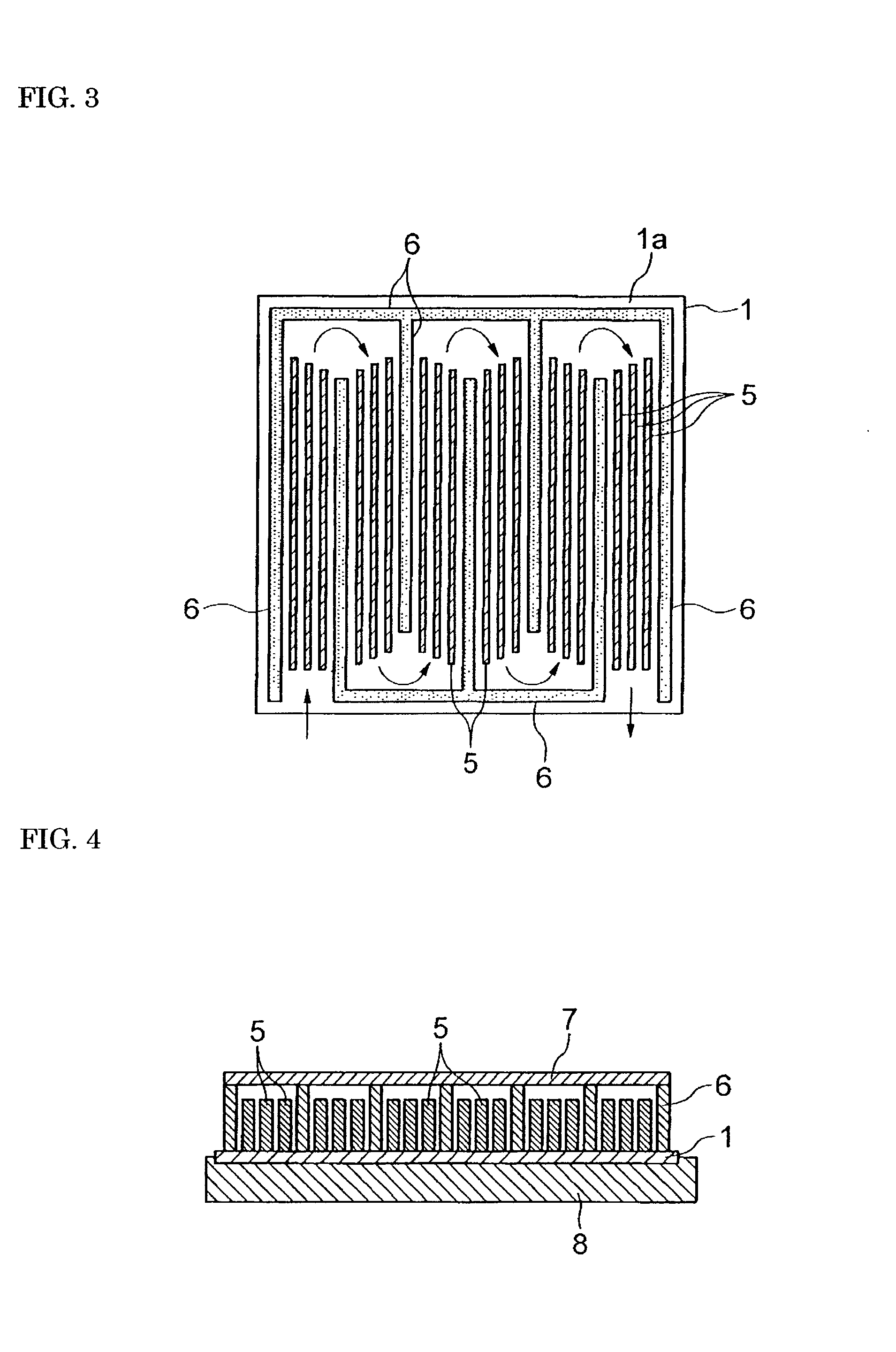
[0040] Heating elements and electrodes were formed on each of ceramic substrates of the same Compositions 1 through 5 as in Example 1, and subsequently aluminum was applied by vacuum deposition so as to form a layer having a thickness of 3 .mu.m on a fluid-heating surface, on which the heating elements were not formed. The aluminum layer thus formed was partially removed by machining, and, as shown in FIG. 3, a meandering, zigzag water channel alternately turning at 180 degrees was formed by aluminum walls 6 and ceilings (not shown) on the remaining aluminum layer. Thereafter, a plurality of aluminum fins 5 were disposed in the water channel, and were bonded to the aluminum layer respectively by an aluminum-brazing material (0.2 mm in thickness) at 600.degree. C. in a vacuum. Arrows in FIG. 3 denote directions in which the water flows.

[0041] Thereafter, a hose was connected so that the water could flow in the water channel where the fins 5 were disposed, and these were mounted as a ...

example 3

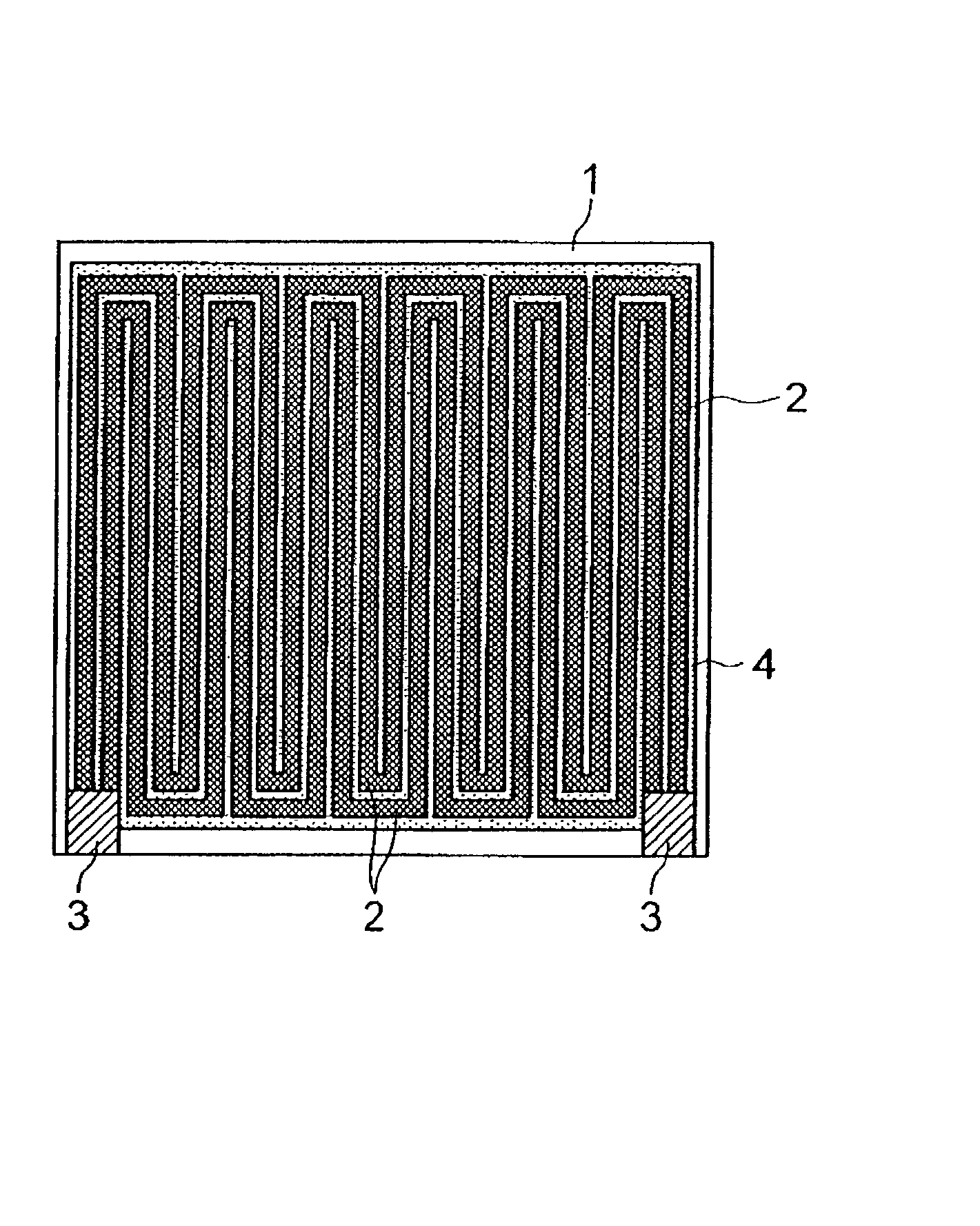
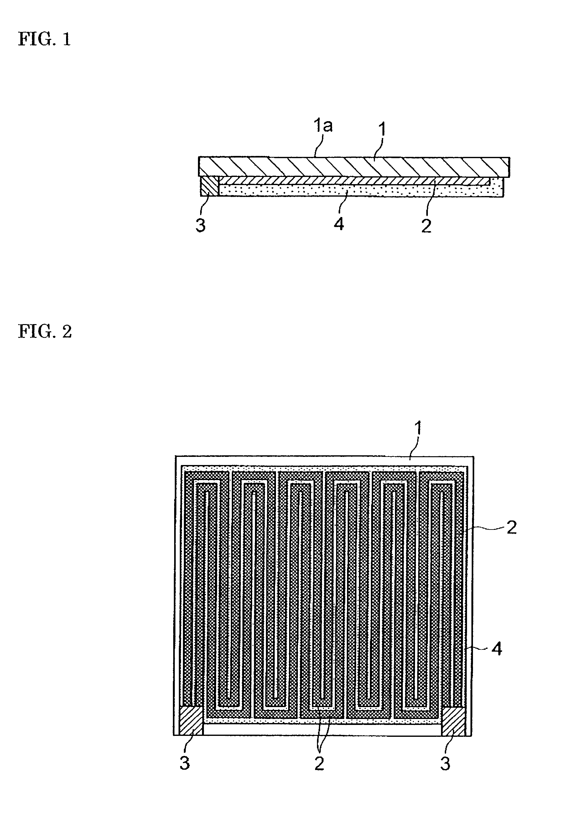
[0042] W-paste heating elements and W-paste electrodes were applied in the shapes shown in FIG. 2 by screen printing onto sheet-like molded ceramic bodies that had the same Compositions 1 through 5 as in Example 1. Further, a W paste was also applied by screen printing onto the whole of the surface having no heating elements, and these were subjected to simultaneous sintering under the same conditions as in Example 1. The same glass paste as in Example 1 was applied by screen printing onto the W heating elements of each ceramic substrate that had been obtained, and subsequently baked in a nitrogen atmosphere so that the W heating elements might not be oxidized, whereby an insulating layer was formed.

[0043] Thereafter, a Ni--P plating was formed in a thickness of 2 .mu.m on the whole of the fluid-heating surface, which is the opposite side relative to the electrodes and W heating elements, of each ceramic substrate. A water channel shaped as shown in FIG. 3 was formed on the plated s...

example 4

[0045] Sheets having the same Compositions 1 through 5 as in Example 1 were formed to have a thickness of 0.318 mm after sintering, which is half as compared with the thickness in Example 1. Thereafter, heating elements and electrodes were formed by screen printing, applying a W-paste onto one surface of the sheet-like ceramic molded bodies in the same way as in Example 3. Further, the surface on which the W paste was screen printed as described above was laminated with a sheet having the same compositions and the same thickness as the above-mentioned sheet-like ceramic molded body and having cut parts through which the electrodes were to be exposed, and the whole thereof was simultaneously sintered. Thereafter, aluminum was deposited by vapor deposition on both surfaces of each of the ceramic substrates thus obtained that includes the heating elements, and a water channel was formed thereon in the same way as in Example 2.

[0046] Subsequently, a plurality of aluminum fins were dispo...


PUM

PropertyMeasurementUnit
thermal conductivityaaaaaaaaaa
water temperatureaaaaaaaaaa

Abstract

The invention provides a fluid heater in which the efficiency of heat transfer to a fluid is improved, downsizing of the heater itself can be achieved, and the rise time until warm water heated to a necessary temperature is supplied is shortened, which results in reduction of the power consumption. The heater includes a flat ceramic substrate (1) and a beating element formed on one surface of or in the interior of the ceramic substrate (1). The ceramic substrate (1) is made of AlN, etc. or silicon nitride, whose thermal conductivity is 50W / m.K or more. A zigzag water channel is formed by walls 6, etc., on the fluid-heating surface of the ceramic substrate (1). A plurality of fins 5 are fixed in the water channel. A heat insulating material 8 can be mounted so as to cover a surface excluding the fluid-heating surface of the ceramic substrate (1).

Description

[0001] This invention relates to a fluid heater for heating a fluid, and, more particularly, to a fluid heater suitable for heating cleaning water used for a warm-water cleaning toilet seat.[0002] Generally, a warm-water cleaning toilet seat jets warm water from a fixed nozzle provided at a rear lower part of the toilet seat and washes a specific part of the human body with the warm water. In the toilet seat, warm water heated to a predetermined temperature is conventionally used to improve the comfort of cleaning.[0003] However, in the conventional warm-water cleaning toilet seat, a method is employed in which water is pre-stored in a water storage tank, is thereafter heated to a predetermined temperature by a sheathed heater or the like, and is kept warm, in order to quickly use warm water for cleaning. Therefore, the drawback of the method is that the water in the water storage tank must continue to be kept warm even while it is not used, and, as a result, the power consumption o...

Claims


Application Information

Patent Timeline
Patent Type & Authority Applications(United States)
IPC IPC(8): E03D9/08F24H1/10H05B3/10H05B3/14H05B3/16H05B3/26H05B3/30
CPCF24H1/102H05B3/141H05B3/265H05B2203/003F24H1/10
Inventor NATSUHARA, MASUHIRONAKATA, HIROHIKO
Owner SUMITOMO ELECTRIC IND LTD
Why Eureka
Try Eureka