

Power generating device
a power generation device and power technology, applied in the direction of electric generator control, dynamo-electric converter control, ac network to reduce harmonics/ripples, etc., can solve the problems of unacceptably high dc voltage, unusable fluctuations in dc voltage capacitor damage or destruction of dc voltage intermediate circuit,
Inactive Publication Date: 2003-03-27
ABB (SCHWEIZ) AG
View PDF28 Cites 21 Cited by
- Summary
- Abstract
- Description
- Claims
- Application Information
AI Technical Summary
Benefits of technology
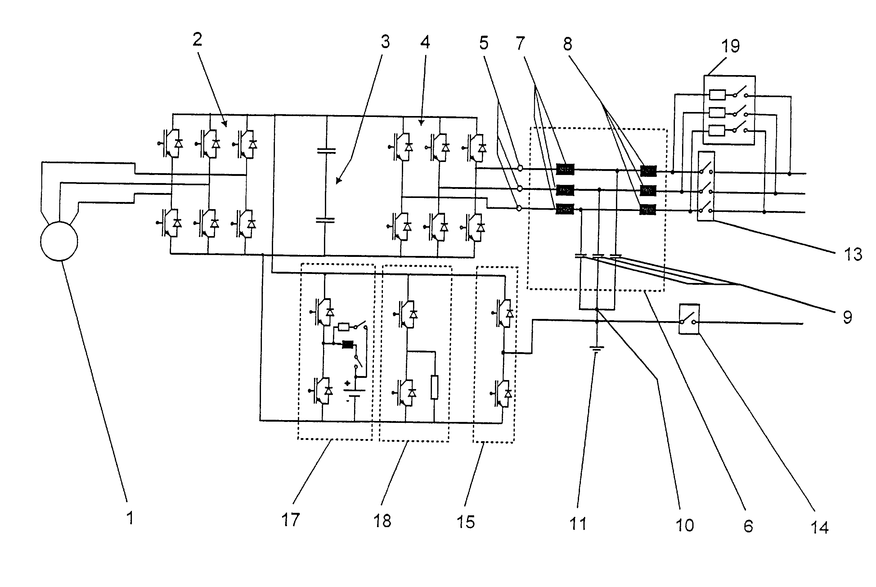
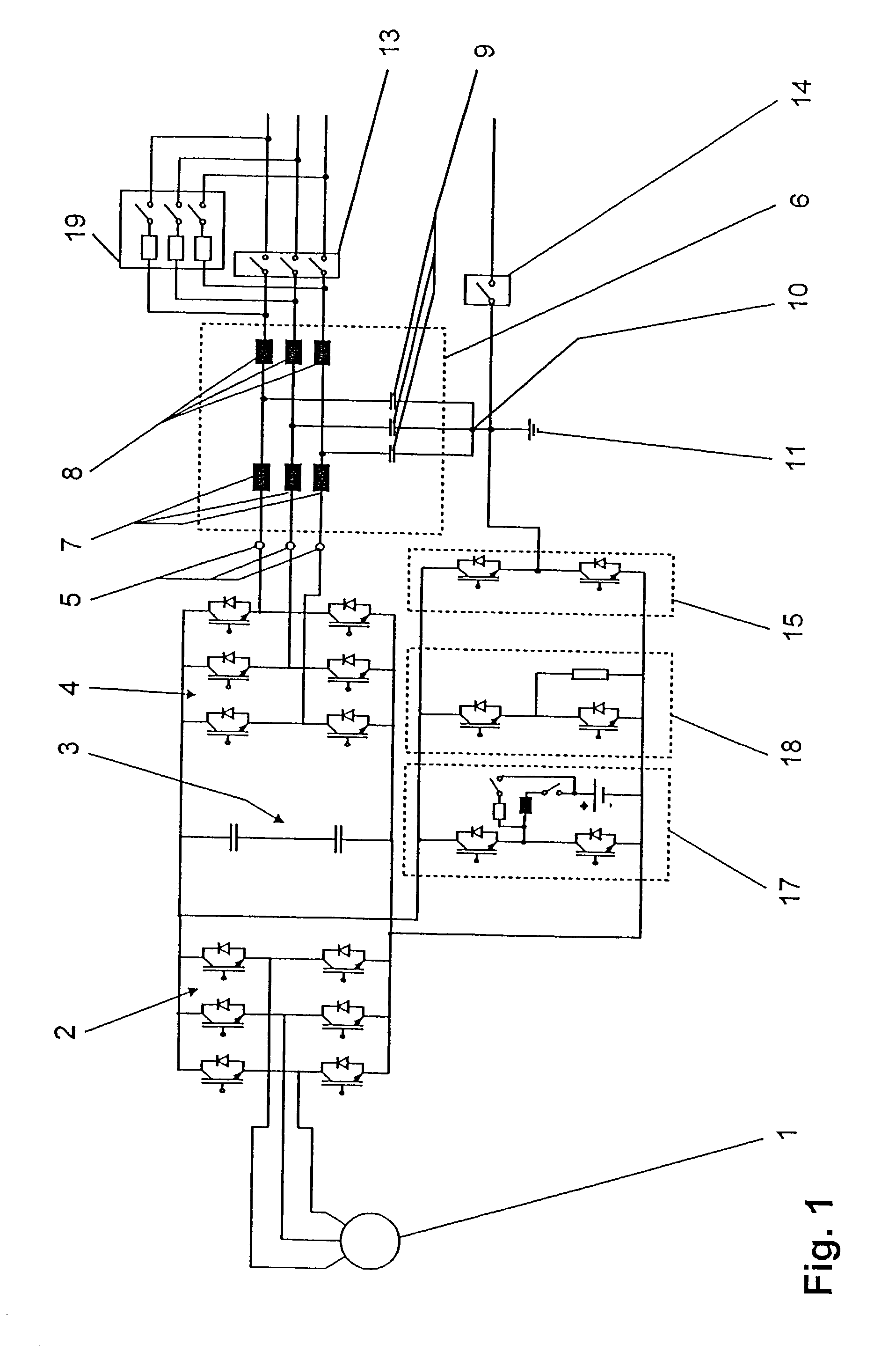
[0006] The power generating device according to the invention comprises a generator which is coupled to a drive unit, in particular to a turbine, and is connected via a rectifier to a DC voltage intermediate circuit, with an inverter being provided, which is connected to the DC voltage intermediate circuit and, on the AC voltage output side, has n phases with n AC voltage connections. A filter arrangement is also connected to the AC voltage connections of the inverter. According to the invention, the filter arrangement has a first filter inductance and a second filter inductance, which is connected in series with the first, for each AC voltage connection, with a filter capacitor being connected to the junction point of the first filter inductance and the second filter inductance. Furthermore, the filter capacitors are connected in a star circuit. This filter arrangement advantageously allows disturbances in an electrical AC voltage supply network which can be connected to the filter arrangement to be very largely kept away from the inverter, since the filter arrangement represents a high input impedance, seen from the electrical AC voltage supply network. Furthermore, signals which are modulated onto the network voltage of the electrical AC voltage supply network, such as ripple control signals, can pass through the filter arrangement without being significantly filtered out.
[0007] In one preferred embodiment of the power generating device according to the invention, a balancing apparatus is provided, which is connected to the DC voltage intermediate circuit and is formed from two series-connected controllable power semiconductor switches, each having a back-to-back parallel-connected diode. According to the invention, the junction point of the power semiconductor switches is connected to the star point of the filter capacitors. The star point thus advantageously forms a neutral point connection, for example for a neutral point of an island network which is to be fed in addition to the electrical AC voltage supply network. A further advantage is that any current flowing via this neutral point connection, in particular with a DC component and / or an alternating component, and in particular an alternating component of relatively high frequency, will have no significant influence on the way in which the voltage is split in the DC voltage intermediate circuit of the power generating device, so that the DC voltage which is present in the DC voltage intermediate circuit is not significantly influenced by such disturbances. Furthermore, the balancing apparatus advantageously makes it possible to set the neutral point to a potential which can be predetermined.
Problems solved by technology
The balancing apparatus which has been mentioned above is subject to the problem that undesirable fluctuations can occur in the DC voltage of the DC voltage intermediate circuit in the case of an alternating component, particularly if any current via the neutral point connection has a relatively high-frequency alternating component.
However, charging of the DC voltage intermediate circuit can lead to an unacceptably high DC voltage in the DC voltage intermediate circuit, which can lead to a flashover as a result of which the DC voltage intermediate circuit, in particular the capacitors as well as the components of the rectifier and of the inverter, may be damaged or destroyed.
Furthermore, a DC component such as this as well as any alternating component that the current via the neutral point connection may have leads to a shift in the voltage relationships on the two capacitors in the DC voltage intermediate circuit.
This can lead to an unacceptably high voltage on one of the capacitors, which can damage or destroy that capacitor.
In the event of any disturbances in the electrical AC voltage supply network, a filter arrangement as mentioned above cannot keep such disturbances away from the inverter in the power generating device, by virtue of its design with a filter capacitor and a filter inductance.
Method used
View moreImage
Smart ImageViewing Examples

Examples
first embodiment
[0010] FIG. 1 shows a power generating device according to the invention,
second embodiment
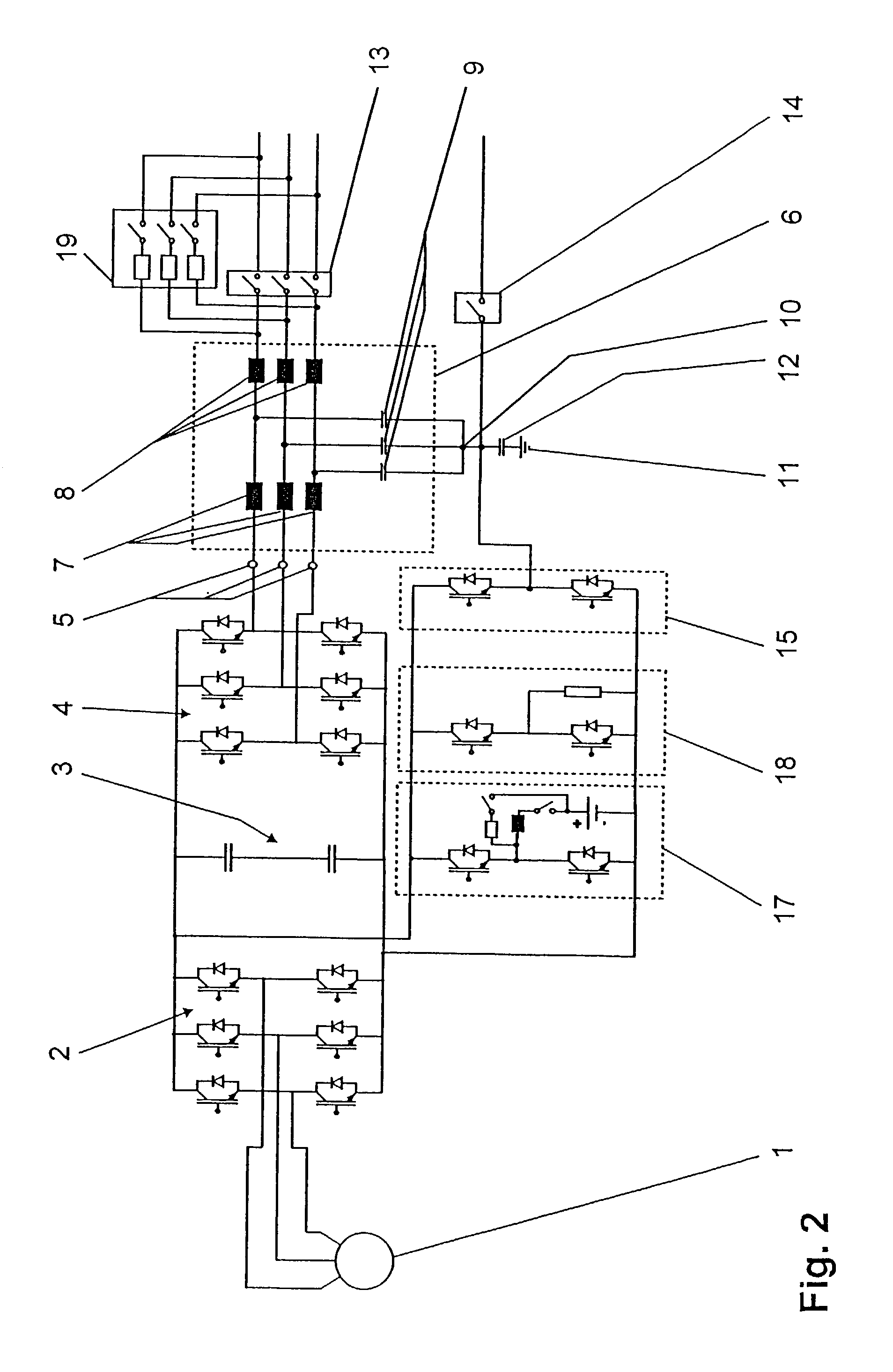
[0011] FIG. 2 shows a power generating device according to the invention,
third embodiment
[0012] FIG. 3 shows a power generating device according to the invention,
Login to View More PUM
 Abstract
A power generating device is specified, which comprises a generator (1) , which is coupled to a drive unit, in particular to a turbine, and is connected via a rectifier (2) to a DC voltage intermediate circuit (3), an inverter (4), which is connected to the DC voltage intermediate circuit (3) and, on the AC voltage output side, has n phases with n AC voltage connections (5), and a filter arrangement (6), which is connected to the AC voltage connections (5). Furthermore, the filter arrangement (6) has a first filter inductance (7) and a second filter inductance (8), which is connected in series with the first, for each AC voltage connection (5), with a filter capacitor (9) being connected to the junction point of the first filter inductance (7) and the second filter inductance (8), and the filter capacitors (9) being connected to one another in a star circuit at a star point (10).
Description
[0001] The present invention relates to the field of power generation. It relates in particular to a power generating device which can be connected in particular to a public AC voltage supply network and / or to an island network, as claimed in the precharacterizing clause of the independent claim.PRIOR ART[0002] Nowadays, power generating devices are used mainly to generate additional electrical power for conventional electrical AC voltage supply networks and / or for supplying island networks in remote areas. One such power generating device is disclosed, by way of example, in U.S. Pat. No. 5,903,116. In this document, the power generating device has a drive unit, which is in the form of a turbine. The drive unit is coupled to a generator, which is connected to a DC voltage intermediate circuit via a passive rectifier. The DC voltage intermediate circuit is formed from two capacitors, which are used as an electrical energy store. Furthermore, the DC voltage intermediate circuit is con...
Claims
Login to View More Application Information
Patent Timeline
 Patent Type & AuthorityApplications(United States)
IPC IPC(8): H02J3/01H02J7/34H02M1/12H02M5/458H02P9/10
CPCH02J3/01H02J7/345H02M1/126H02M5/4585H02P9/105Y02E40/40
InventorHOFSTETTER, BRUNOGOLLE, INGORONNER, BEATMULLIS, MARTIN
OwnerABB (SCHWEIZ) AG