Passively Q-switched laser

a laser and q-switching technology, applied in the direction of laser details, light demodulation, instruments, etc., can solve the problems of reducing the pulse interval of the outputted laser beam, and failing to increase the peak intensity (pulse energy) of the laser

Inactive Publication Date: 2003-04-03
HAMAMATSU PHOTONICS KK
View PDF2 Cites 13 Cited by
  • Summary
  • Abstract
  • Description
  • Claims
  • Application Information

AI Technical Summary

Benefits of technology

[0008] In conventional practice, increasing the intensity of a laser beam emitted from a semiconductor laser has been thought to be the equivalent of increasing the temporal peak intensity of a laser beam outputted from a passively Q-switched laser. Consequently, in order to improve the spatial peak intensity of laser beam output in a conventional passively Q-switched laser, it has been standard practice to minimize the thickness of the laser beam emitted from a condensing optical system and to direct the bean to the surface of a solid-state laser medium.

Problems solved by technology

In practice, however, adopting such techniques merely leads to a reduction in the pulse interval of the outputted laser beam and fails to increase the peak intensity (pulse energy) of the laser beam outputted from a passively Q-switched laser (see FIG. 6).

Method used


Image

  • Passively Q-switched laser
  • Passively Q-switched laser
  • Passively Q-switched laser

Examples


Embodiment Construction

[0042] The above-mentioned passively Q-switched laser was manufactured by way of trial and the characteristics thereof were evaluated.

Experimental Conditions

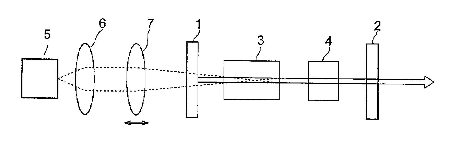
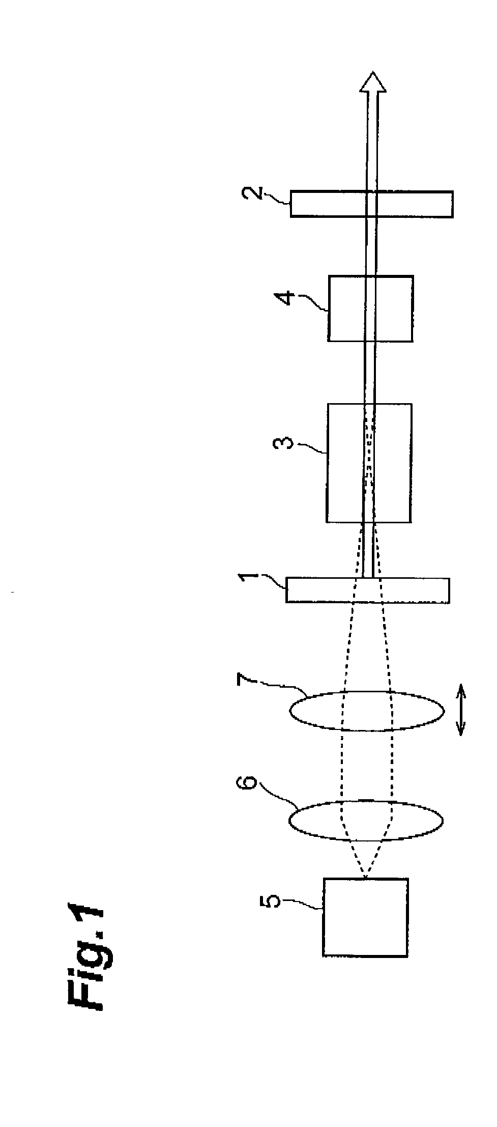
[0043] The elements used in the experiment were as follows: the maximum value of the drive current pulse supplied to the semiconductor laser 5 was 40 A (temporal peak intensity of the excitation laser beam: 25 W), the cycle frequency of the drive current pulse was 100 Hz (pulse width: 500 .mu.s), and the duty ratio was 5%.

1 TABLE I Semiconductor laser 5: Active Layer Material: AlGaAs Emitted Light Wavelength: 808 nm Solid-State Laser Medium 3: Host Material: Y.sub.3Al.sub.5O.sub.12 Dopant: Nd.sup.34 Dopant Concentration: 1.4 at % Fluorescence Wavelength: 1064 nm Host Crystal 4: Host Material: Y.sub.3A.sub.5O.sub.12 Dopant: Cr.sup.41 Absorption Waveband: 1064 nm .+-. 250 nm Initial Transmittance: 30% Reflective Mirror 1: Reflectivity: 99.9% (wavelength: 1064 nm) Transmittance: 99.9% (wavelength: 808 nm) Reflective Mirror 2: Refle...


PUM


Abstract

The present passively Q-switched laser comprises a condensing optical system for condensing a laser beam emitted from a laser light source onto the surface of the solid-state laser medium. The surface of a solid-state laser medium is disposed off the condensation position of the laser beam produced by the condensing optical system,

Description

[0001] 1. Field of the Invention[0002] The present invention relates to a passively Q-switched laser.[0003] 2. Description of the Related Art[0004] A conventional device comprises a solid-state laser medium disposed between a pair of reflective mirrors that constitute a resonator, a host crystal for absorbing the fluorescence generated from the solid-state laser medium in the resonator and increasing transmittance in accordance with the absorption, a semiconductor laser for emitting a laser beam that excites the solid-state laser medium, and a condensing optical system for condensing the laser beam emitted from the semiconductor laser onto the surface of the solid-state laser medium.[0005] When the host crystal absorbs a laser beam from the semiconductor laser, the electron density of the excitation levels in the host crystal gradually increases, and because the excitation levels become filled at one point, the electron density is saturated, transparency is achieved, the Q-value of ...

Claims


Application Information

Patent Timeline
Patent Type & Authority Applications(United States)
IPC IPC(8): H01S3/113
CPCH01S3/005H01S3/113H01S3/1022H01S3/09415
Inventor SAKAI, HIROSHISONE, AKIHIROKAN, HIROFUMITAIRA, TAKUNORI
Owner HAMAMATSU PHOTONICS KK
Why Eureka
Try Eureka