Apparatus and method in a network switch port for transferring data between buffer memory and transmit and receive state machines according to a prescribed interface protocol

a network switch and buffer memory technology, applied in the field of network switches, can solve the problems of increasing the cost and complexity of the network switch, increasing the latency of the buffering process, and increasing the complexity of maintaining the status information for each data frame stored in the fifo buffer

Inactive Publication Date: 2003-04-17
GLOBALFOUNDRIES INC
View PDF0 Cites 103 Cited by
  • Summary
  • Abstract
  • Description
  • Claims
  • Application Information

AI Technical Summary

Problems solved by technology

One disadvantage with the use of a FIFO for a transmit buffer or a receive buffer is the increased latency encountered during the buffering process.
An additional disadvantage with the use of a FIFO or transmit buffer or receive buffer is the increasing complexity associated with maintaining status information for each data frame stored in the FIFO buffer.
Moreover, additional synchronization logic would be required to maintain correspondence between the stored frame data and the corresponding status data, increa

Method used


Image

  • Apparatus and method in a network switch port for transferring data between buffer memory and transmit and receive state machines according to a prescribed interface protocol
  • Apparatus and method in a network switch port for transferring data between buffer memory and transmit and receive state machines according to a prescribed interface protocol
  • Apparatus and method in a network switch port for transferring data between buffer memory and transmit and receive state machines according to a prescribed interface protocol

Examples


Embodiment Construction

[0021] The present invention will be described with the example of a switch in a packet switched network, such as an Ethernet (IEEE 802.3) network. It will become apparent, however, that the present invention is also applicable to other packet switched systems, as described in detail below, as well as to other types of systems in general.

Switch Architecture Overview

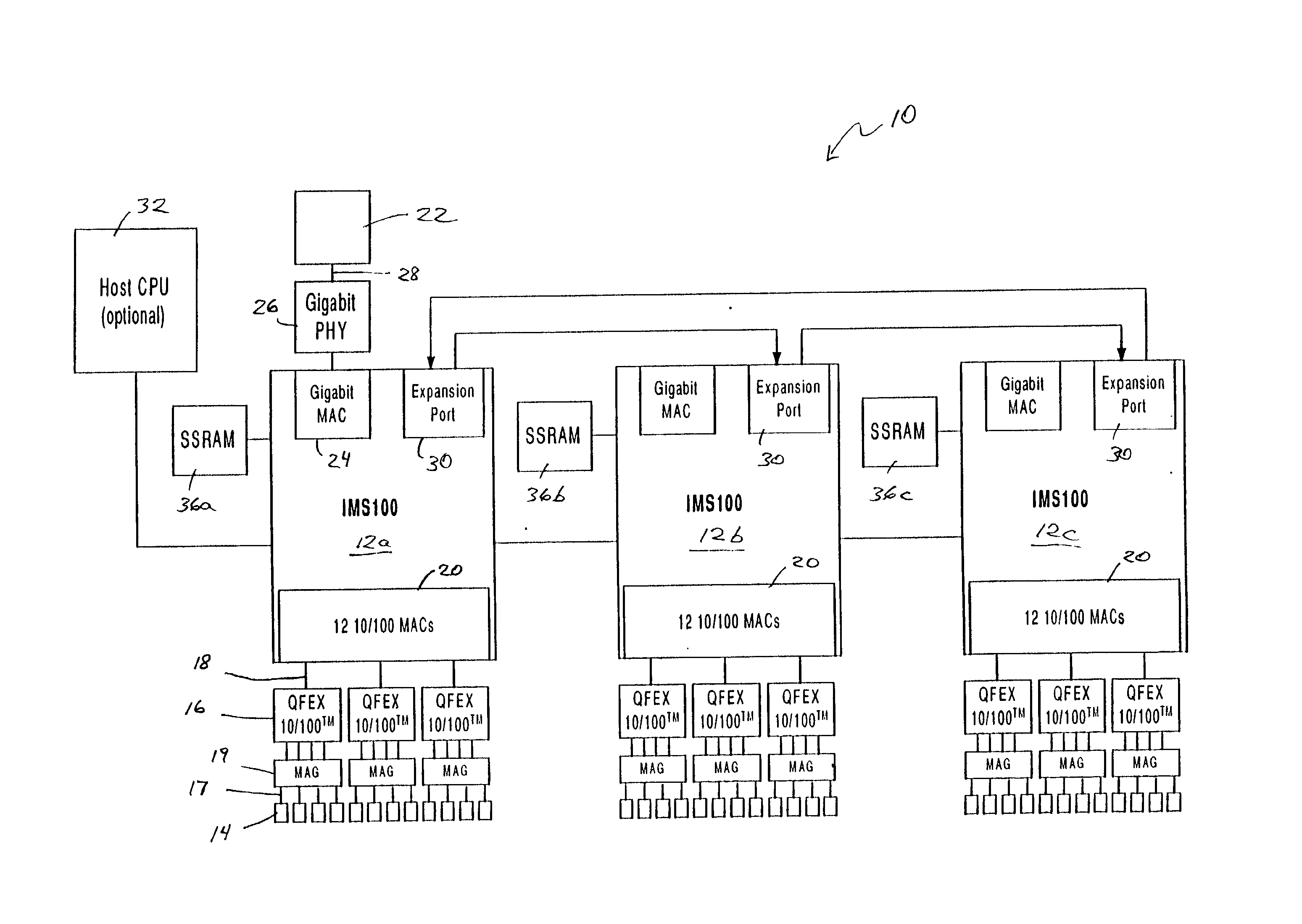
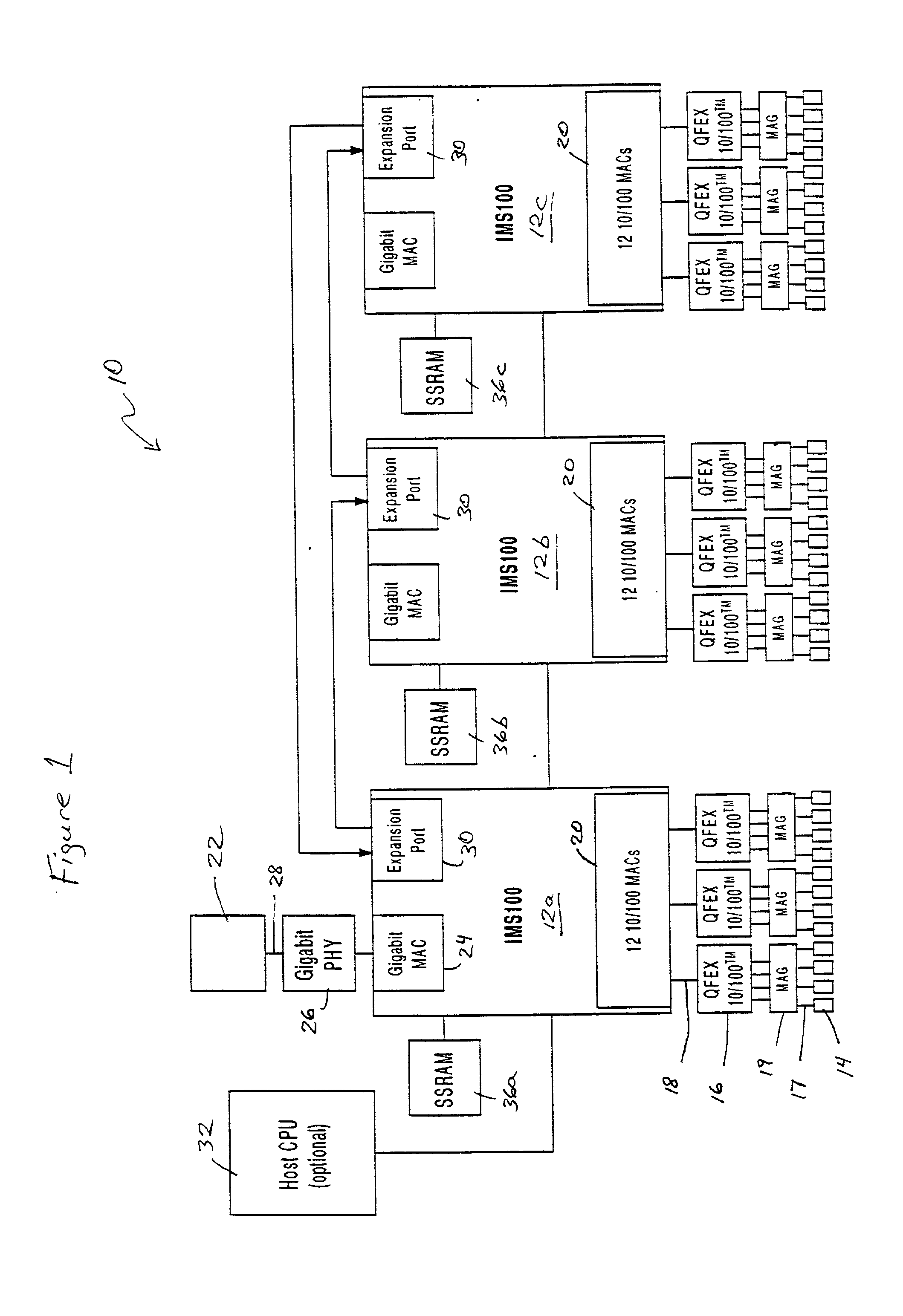
[0022] FIG. 1 is a block diagram of an exemplary system in which the present invention may be advantageously employed. The exemplary system 10 is a packet switched network, such as an Ethernet (IEEE 802.3) network. The packet switched network includes integrated multiport switches (IMS) 12 that enable communication of data packets between network stations. The network may include network stations having different configurations, for example twelve (12) 10 megabit per second (Mb / s) or 100 Mb / s network stations 14 (hereinafter 10 / 100 Mb / s) that send and receive data at a network data rate of 10 Mb / s or 100 Mb / s, and a 1000 ...


PUM


Abstract

A network switch in a packet switched network includes a plurality of network switch ports, each configured for sending and receiving data packets between a medium interface and the network switch. The network switch port includes an IEEE 802.3 compliant transmit state machine and receive state machine configured for transmitting and receiving network data to and from a medium interface, such as a reduced medium independent interface, respectively. The network switch port also includes a memory management unit configured for selectively transferring the network data between the transmit and receive state machines and a random access transmit buffer and a random access receive buffer, respectively. The memory management unit transfers the network data between the transmit and receive state machines and the respective buffers based on prescribed interface protocol signals between the memory management unit and the transmit and receive state machines. Hence, the memory management unit and the transmit and receive state machines transfer data according to a prescribed interface protocol, where a request-based protocol enables data transfers to be performed independent of different clock domains encountered within the network switch port.

Description

[0001] 1. Field of the Invention[0002] The present invention relates to networks and more particularly, to a system and method of controlling network traffic data in a full-duplex switched network operating according to Ethernet (IEEE 802.3) protocol.[0003] 2. Description of the Related Art[0004] Switched local area networks use a network switch for supplying data frames between network stations or other network nodes, where each network node is connected to the network switch by a media. The switched local area network architecture uses a media access control (MAC) enabling a network interface within each network node and the network switch to access the media. The network switch stores and forwards data frames received from a transmitter node to a destination node based on header information and the data in the received frames, including source and destination address. An external memory, such as an SSRAM, is used by the network switch to temporarily store the data frames as they ...

Claims


Application Information

Patent Timeline
IPC IPC(8): H04L12/28
CPCH04L12/2854
Inventor NIU, AUTUMN JANEFISCHER, JENNY LIU
Owner GLOBALFOUNDRIES INC
Why Eureka
Try Eureka