Multi-stage vacuum pump

a vacuum pump and multi-stage technology, applied in the direction of positive displacement liquid engines, piston pumps, liquid fuel engines, etc., can solve the problems of pump overload, large temperature differential between them, and increase the temperature of the housing of multi-stage vacuum pumps

Inactive Publication Date: 2003-04-24
AISIN SEIKI KK
View PDF4 Cites 22 Cited by
  • Summary
  • Abstract
  • Description
  • Claims
  • Application Information

AI Technical Summary

Problems solved by technology

While the multi-stage vacuum pump is in operation, the resulting compression load generates a heat of compression, which increases the temperature of the housing of the multi-stage vacuum pump.
As well known, the heat of compression becomes much larger at an exhaust or outlet port than the inlet or suck port, in resulting very large temperature differential therebetween.
Thus, when such a specific gas is sucked, the resulting gas is cooled down, in the pumping chamber of earlier stage which is relative low in temperature, below a temperature of solidification, which causes the gas to solidify or condense, resulting in a deposit at a portion such as an interface between the rotor and the housing in the pumping chamber, whereby drawbacks may occur such as pump overload when the rotors in rotation and / or stopping the rotation of each of the rotors.
In "Roots"-type vacuum pumps, in general noise generation is at issue which results from particular that the Roots profile rotors in the chamber adjacent the pump outlet expelling discrete trapped volumes of evacuated gas to atmosphere from between the Roots rotors.
However, in the above-described conventional "Roots"-type vacuum pump, the compression heat generation is caused by the compression work at each of pumping chambers such that the compression work becomes larger at higher stage pumping chamber.
This causes a thermal gap or temperature differential between the inlet port and outlet port.
Thus, when such a gas is sucked, the resulting gas is cooled down, in the pumping chamber of earlier stage which is relative low in temperature, below a temperature of solidification, which causes the gas to solidify or condense, resulting in a deposit at a portion such as an interface between the rotor and the housing in the pumping chamber, whereby drawbacks may occur such as pump overload when the rotors in rotation and / or stopping the rotation of each of the rotors.
In addition, adding the silencer to the conventional "Roots"-type vacuum pump results in an increase of the number of parts, an increase of production cost, and an increase of mass or outer scale.

Method used


Image

  • Multi-stage vacuum pump
  • Multi-stage vacuum pump
  • Multi-stage vacuum pump

Examples


first embodiment

[0040] [First Embodiment]

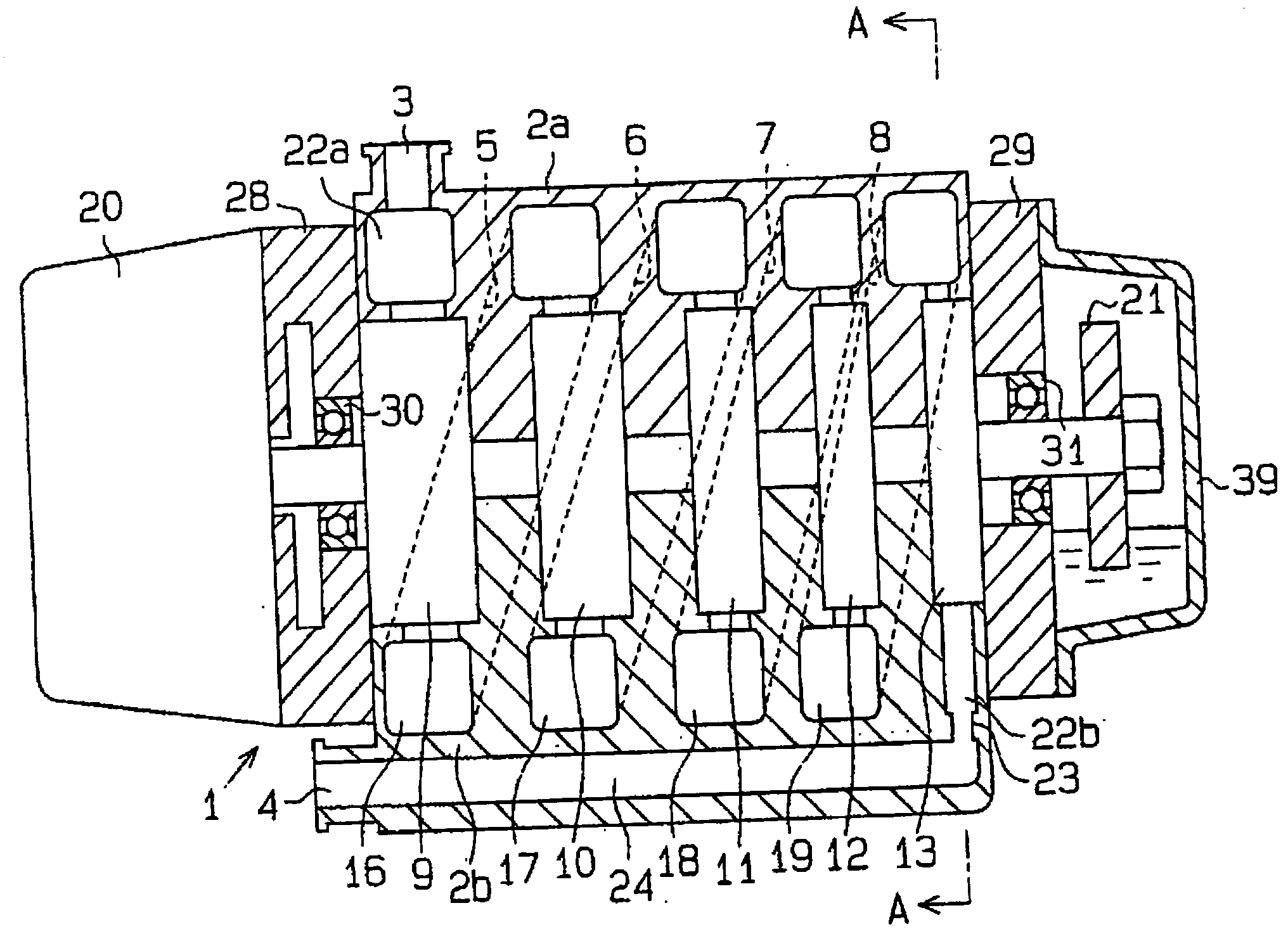
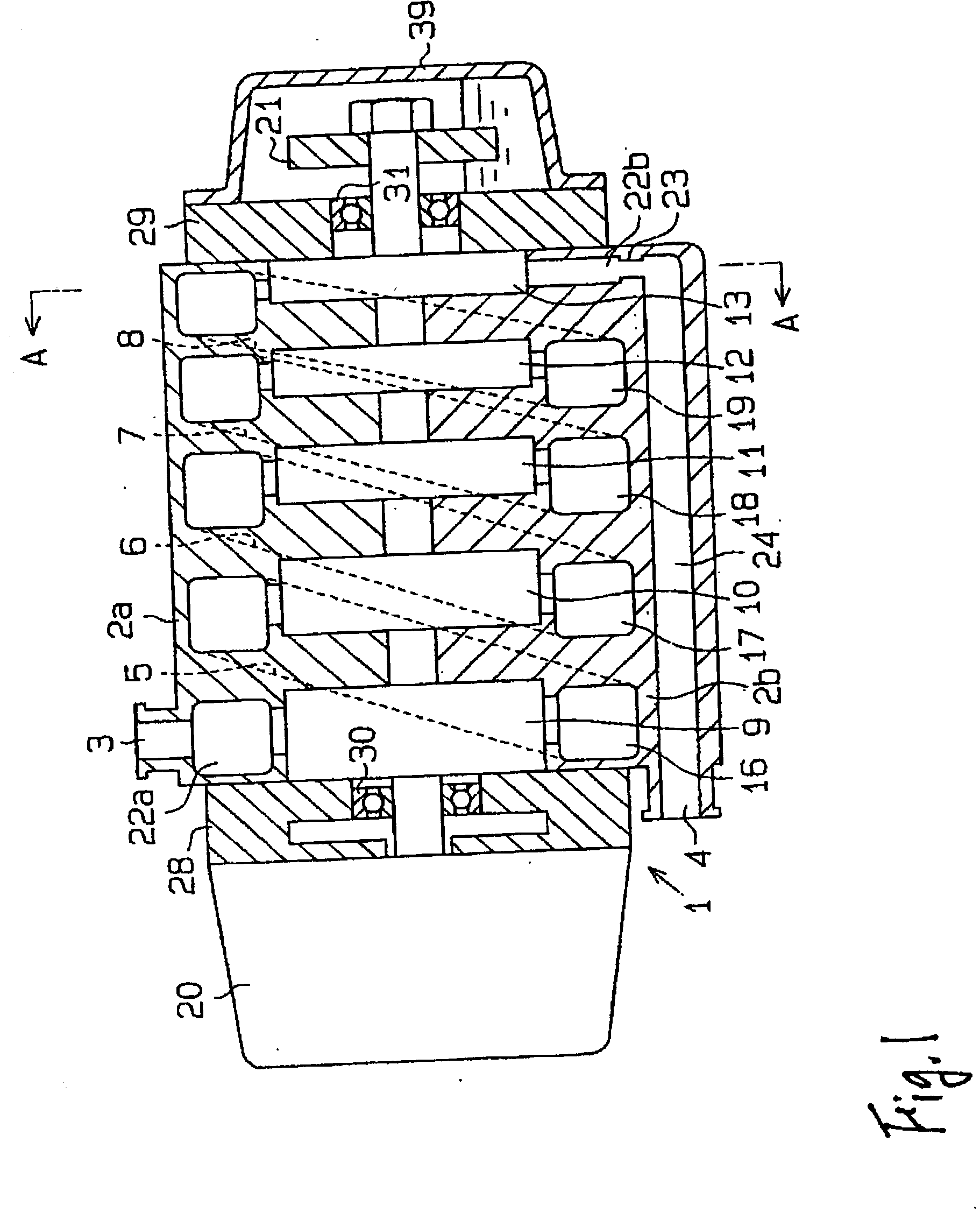
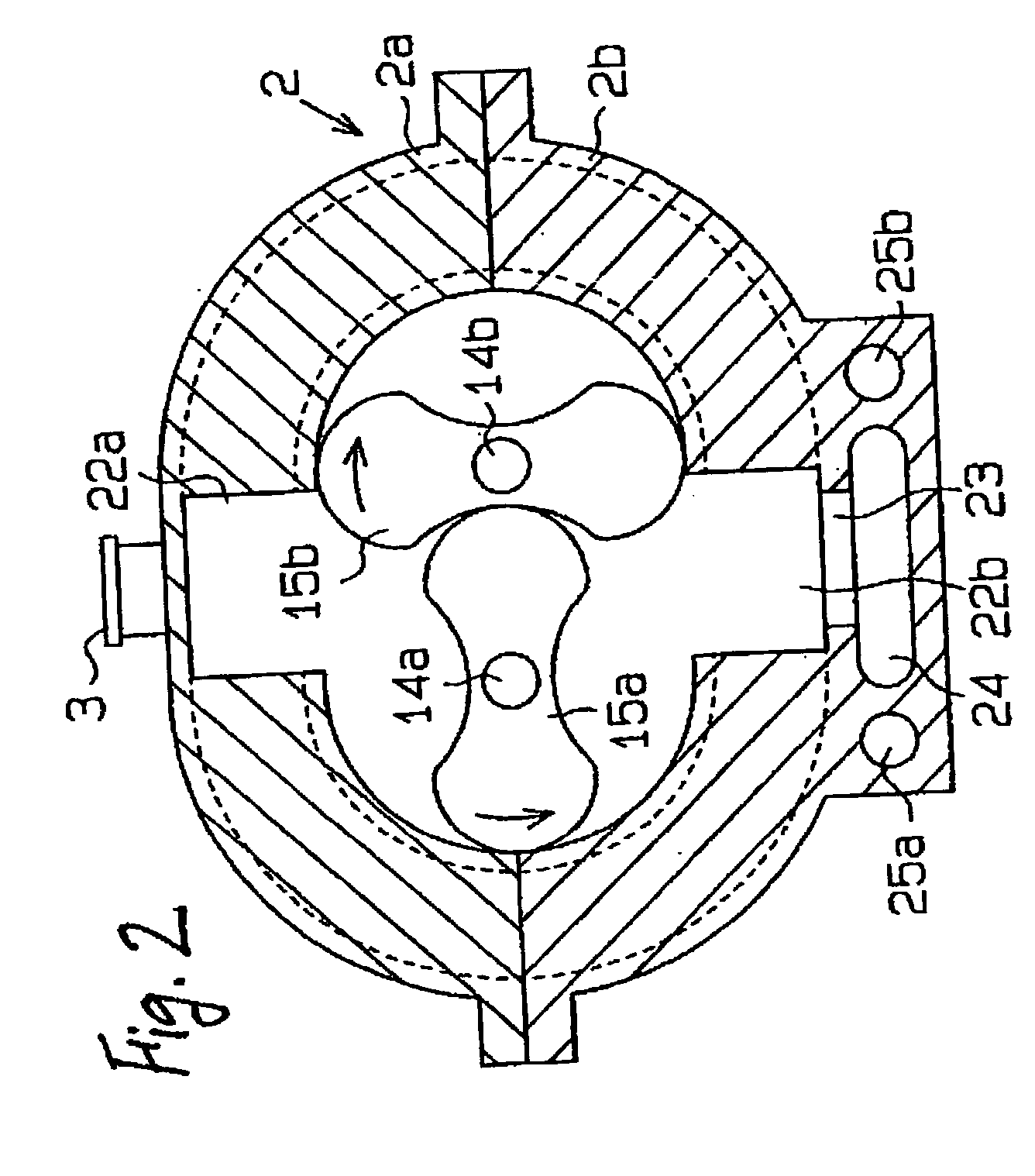
[0041] Referring first to FIGS. 1 and 2, there is illustrated a "Roots"-type multi-stage vacuum pump 1 which will be called simply pump. FIG. 1 illustrates an inner structure of the pump 1 and FIG. 2 is a cross-sectional view taken along line A-A in FIG. 1. The pump 1 includes complementary housing members 2a and 2b which constitute a housing 2, a pair of side covers 28 and 29 which are coupled to opposite ends of the housing 2, an electric motor 20 secured to the side cover 28, and an oil cover 39 secured to the side cover 29.

[0042] At a central portion inside the housing 2, as depicted in FIG. 2, there are provided a pair of paralelly arranged shafts 14a and 14b which extend along an axial direction of the housing 2. The housing member 2a is formed at its upper side thereof with an integral inlet port 3. The inlet port 3 is in fluid communication with a space (not shown) to suck a gas stored therein for establishing an evacuated state of the space. The inl...

second embodiment

[0067] [Second Embodiment]

[0068] Referring to FIG. 4, there is illustrated a "Roots"-type multi-stage vacuum pump in accordance with a second embodiment of the present invention. This pump according to the second embodiment is identical with the pump 1 according to the first embodiment except that other than a passage 24a additional passages 24R and 24L are provided which are formed in housing members 2aa and 2ba for surrounding each pumping chamber, respectively. Thus, each pumping chamber is of much wider heat transmission area to which heat is applied from gas passing through the passages 24a, 24R, and 24L.

[0069] In detail as shown in FIG. 4, the passages 24R and 24L are formed in the respective housing members 2aa and 2ba. The passages 24R and 24L are of an arc-shaped cross-section so as to run along the outer profile of each of the pumping chambers 9, 10, 11, 12, and 13. Thus, the high-temperature gas due to heat of compression which passes through the passages 24a and the arc-...

third embodiment

[0070] [Third Embodiment]

[0071] Referring to FIG. 4, there is illustrated a "Roots"-type multi-stage vacuum pump in accordance with a third embodiment of the present invention. This pump according to the third embodiment is identical with the pump 1 according to the first embodiment except that the cooling passages 25a and 25b are inserted therein with corrosion-free tubes 35a and 35b, respectively, for the prevention of possible corrosion of the housing member 2bb.

[0072] In other words, the FIG. 3--illustrated structure according to the third embodiment of the present invention is constructed or configured by modifying the FIG. 2--illustrated structure such that the inserted corrosion-free tubes 35a and 35b are in thermal engagement with the respective cooling passages 25a and 25b by casting, brazing, or other suitable manner. The corrosions tubes 35a and 35b make surely the housing member 2b free from corrosion at the cooling passages 25a and 25b through which the cooling fluid pa...


PUM


Abstract

The present invention provides a multi-stage vacuum pump which includes: a housing in which a plurality of pumping chambers are formed, the pumping chambers being arranged in series and being in fluid communication with one another, one of the pumping chambers which is at one end of the series acting as an initial stage pumping chamber, another of the pumping chamber which is at the other end of the series acting as a final stage pumping chamber, the housing being provided with an inlet port for sucking a gas from a space to be evacuated into the initial stage pumping chamber, the housing being provided with an outlet port for exhausting the gas from the final stage pumping chamber; a Roots-type pump section occupying each of the pumping chambers; and a device for decreasing a temperature differential between the initial stage pumping chamber and the final stage pumping chamber.

Description

[0001] The present application is based on and claims priority under 35 U.S.C .sctn.119 with respect to Japanese Patent Application No.2001-326779 on Oct. 24, 2001 (13th Year of Heisei), the entire content of which is incorporated herein by reference.[0002] 1. Field of the Invention[0003] The present invention is generally directed to a multi-stage vacuum pump and in particular to a multi-stage vacuum pump whose inner structure is improved such that in-vacuum-pump substances which are easy to coagulate are made free from solidification by utilizing heat of compression resulting from generates upon gas compression.[0004] 2. Prior Art[0005] In general a conventional multi-stage vacuum pump of the type is constructed to have a plurality of in-series pumping chambers each of which accommodates a pair of intermeshing rotors which are all of a "Roots"-type profile. The pair of "Roots"-type rotors which are provided in each pumping chamber is rotated therein to make a space evacuated which...

Claims


Application Information

Patent Timeline
Patent Type & Authority Applications(United States)
IPC IPC(8): F04B37/16F04C18/18F04C18/12F04C23/00F04C25/02F04C29/04F04C29/06F04C29/12
CPCF04C18/126F04C23/001F04C29/124F04C29/063F04C29/068F04C29/04
Inventor NAITO, YOSHIHIRONOSO, KAZUONAKAMURA, KAZUAKI
Owner AISIN SEIKI KK
Why Eureka
Try Eureka