

Valve for controlling the flow fluids
a valve and fluid technology, applied in the direction of valve operating means/releasing devices, fuel injecting pumps, machines/engines, etc., can solve the problems of system pressure drop, correspondingly large, cost-intensive dimensioning of actuator units, and adversely affecting the opening behavior of the entire valv
- Summary
- Abstract
- Description
- Claims
- Application Information
AI Technical Summary
Benefits of technology
Problems solved by technology
Method used
Image

Examples
Embodiment Construction
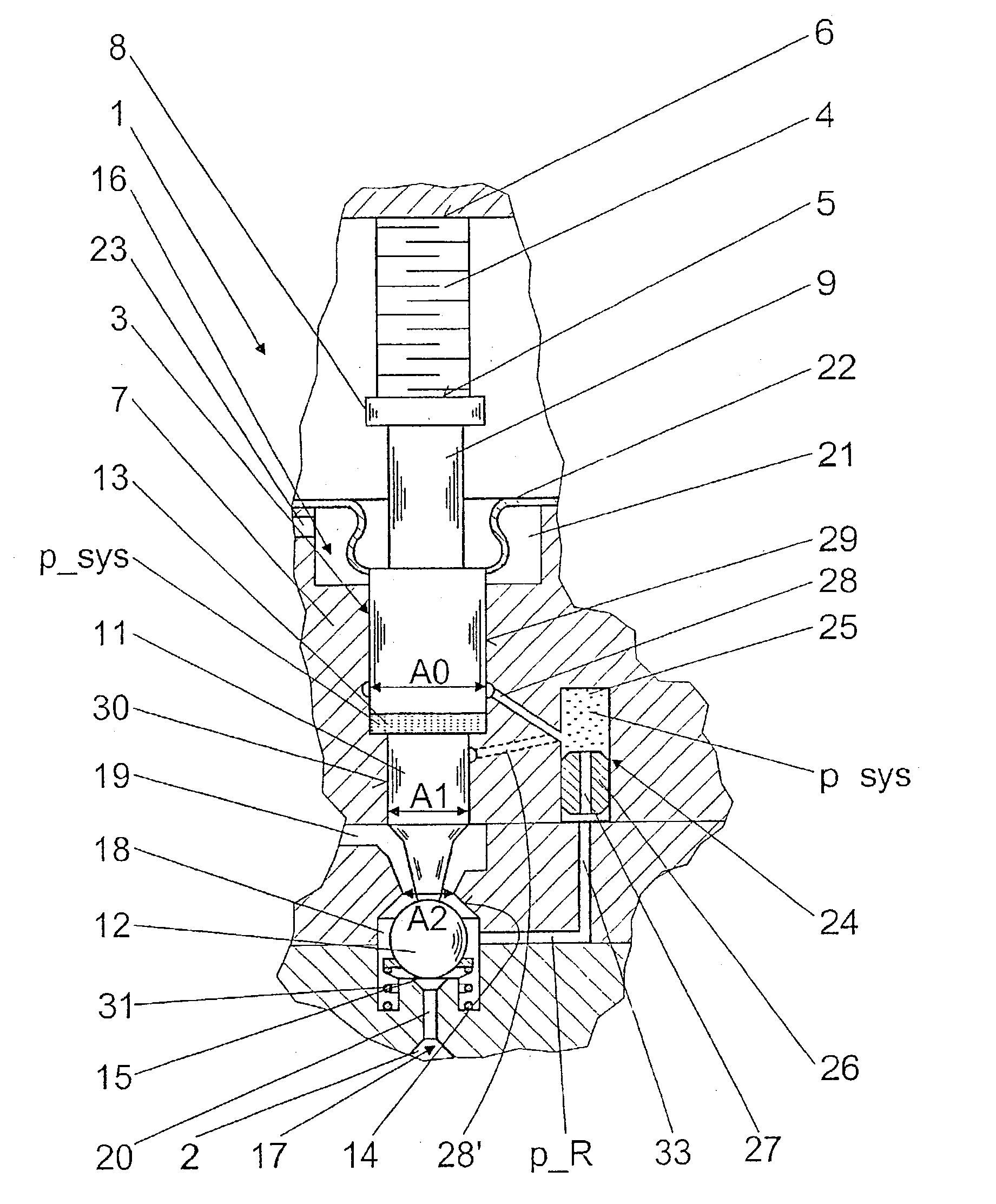
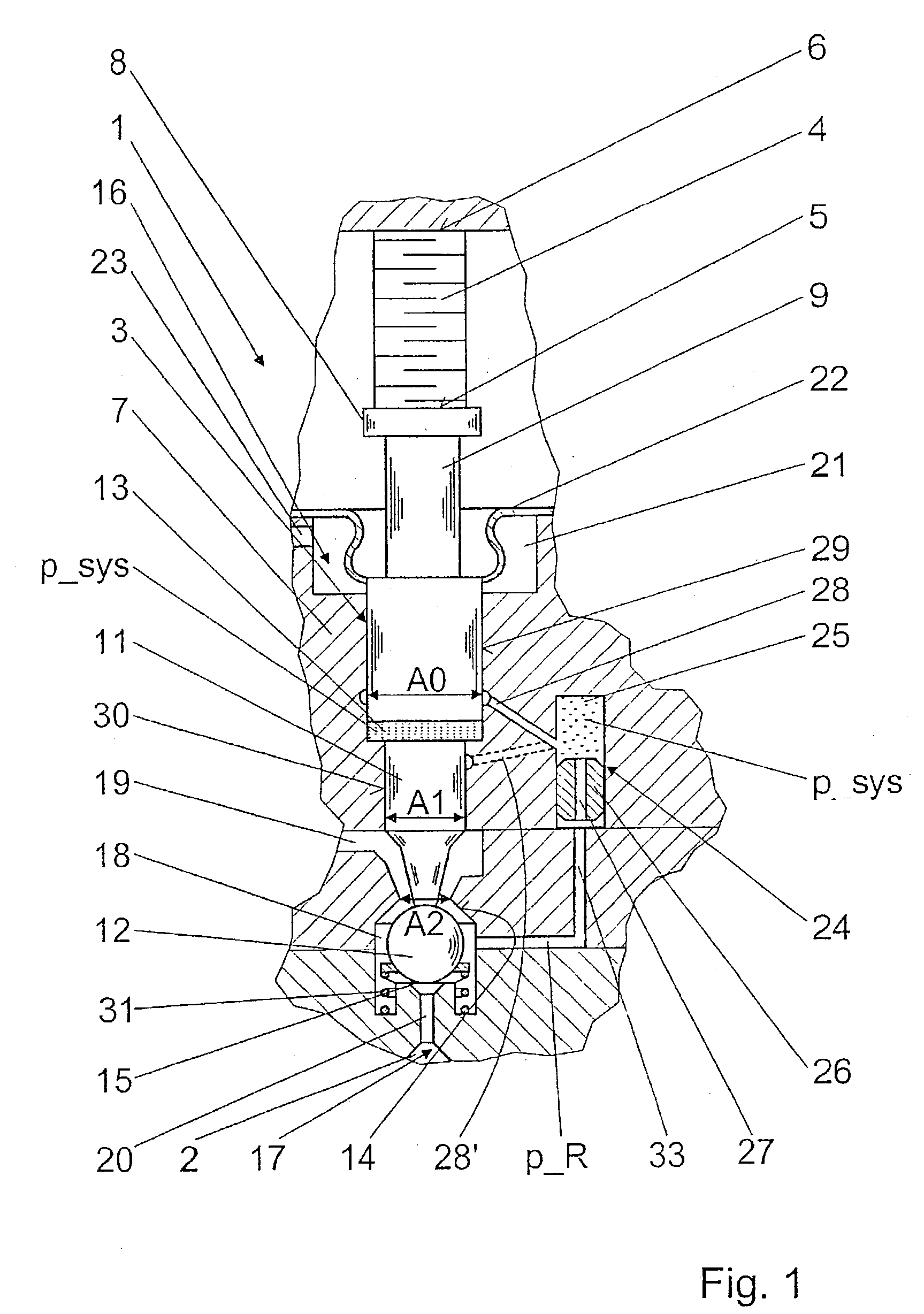
[0013] The exemplary embodiment shown in FIG. 1 illustrates a use of the valve of the invention in a fuel injection valve 1 for internal combustion engines of motor vehicles. In the present embodiment, the fuel injection valve 1 is embodied as a common rail injector for injecting preferably Diesel fuel; the fuel injection is controlled via the pressure level in a valve control chamber 2, which communicates with a supply of high pressure. For adjusting the injection onset, a duration of injection, and an injection quantity via force ratios in the fuel injection valve 1, a valve member 3 is triggered via an actuator unit embodied as a piezoelectric actuator 4, which is disposed on the side of the valve member 3 remote from the valve control chamber and from the combustion chamber. The piezoelectric actuator 4 is constructed in the usual way in a plurality of layers, and on its side toward the valve member 3, it has an actuator head 5, while on its side remote from the valve member 3 i...
PUM
 Abstract
Description
Claims
Application Information