Control cable

a control cable and cable technology, applied in the direction of rigid pipes, water mains, service pipes, etc., can solve the problems of inability to meet the requirements of high-quality alloy steel, disadvantages of dissimilar metals in marine environments, and associated costs of referred techniques, so as to reduce the cost of materials, and reduce the cost

Inactive Publication Date: 2003-06-05
HAVTROLL
View PDF1 Cites 18 Cited by
  • Summary
  • Abstract
  • Description
  • Claims
  • Application Information

AI Technical Summary

Benefits of technology

[0010] It is the objective of the present invention to eliminate the disadvantages identified for the referred techniques and it is aimed at combining low construction cost with cost effective installation techniques. The invention has probably an economical limit related to the number of wells operated by means of a single cable of the proposed
[0012] The invention is aimed at saving material cost, as only lower and less costly steel quality is required due to the novel design. For some scenarios significant costs may be saved associated with installation of the cable. A further objective is to achieve a well control module, which requires fewer control lines (hydraulic) of lower capacity. This may be achieved by means of a modification of the hydraulic circuitry of the well control module.

Problems solved by technology

Particularly lines for supply of hydraulic power fluid require high cleanliness standards and consequently often leads to requirement for high quality alloy steel.
A mixture of dissimilar metals may be disadvantageous in a marine environment.
For development of marginal fields the referred techniques may be associated with undesirable costs.
For some scenarios significant costs may be saved associated with installation of the cable.

Method used


Image

  • Control cable
  • Control cable
  • Control cable

Examples


Embodiment Construction

with references to the enclosed drawings, where

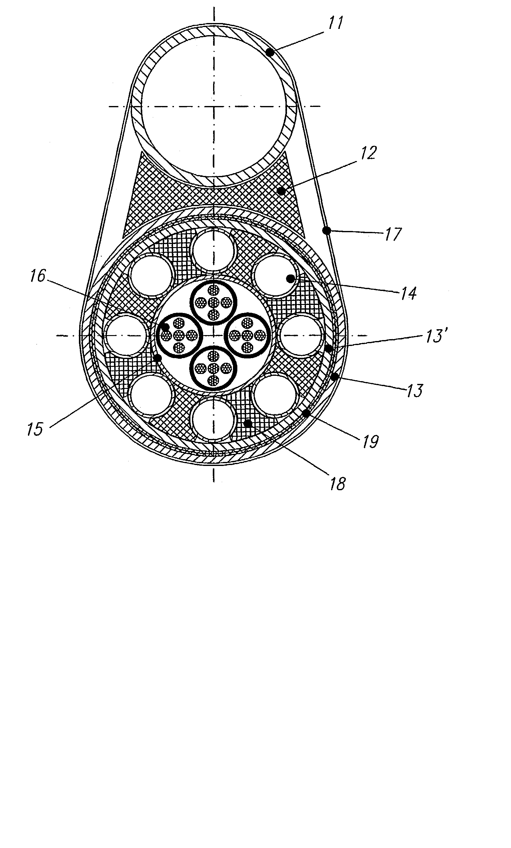
[0015] FIG. 1 shows a service umbilical cord according to state-of-the-art

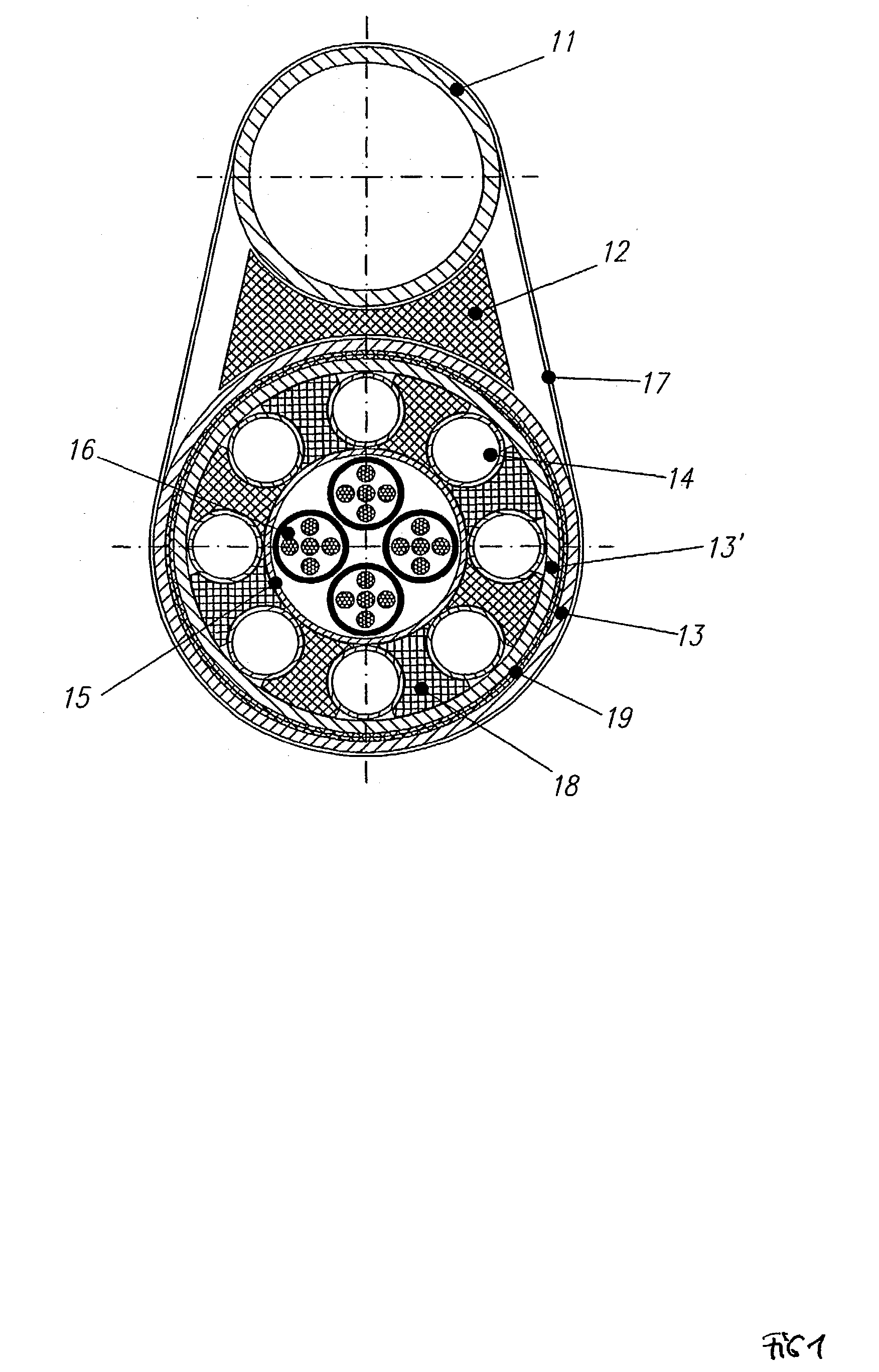
[0016] FIG. 2 shows another service umbilical cord according to state-of-the-art.

[0017] FIG. 3 shows a design of an integrated service umbilical cord according to the present invention

[0018] FIG. 4 shows the principle for conventional hydraulic control of a down hole safety valve, and

[0019] FIG. 5 shows a schematic of the hydraulic control circuits of a control module according to the invention

[0020] The concept is based on use of a regular 2-4" pipe in carbon steel as carrier pipe and conduit for hydrate inhibitor 31. This pipe also provides mechanical protection, stress relief and corrosion protection for all the internal components. All small bore tubing such as conduits for supply of chemicals 32, conduits for hydraulic power fluid (control system) and electrical conductors 33 are accommodated inside the outer carrier 31. The concept is illustrated in FIG. 3, ...


PUM


Abstract

The present invention relates to a cable for supplying chemicals to, and for the control of, a sub-sea hydrocarbon well comprising an external pressure pipe enclosing a number of smaller pipes, the cable having the special features that the external enclosing pipe forms a channel for the hydration inhibiting agent and in addition forms an element that takes up mechanical tension in the cable, protects the internal pipes against radial forces and forms a nearly corrosion free environment protecting the smaller, internal pipes.

Description

[0001] The present invention relates to a control cable (umbilical cord) for sub sea field developments producing hydrocarbons, especially sub sea installations tied back to a central production platform by means of a flow line and an umbilical cord, where the umbilical cord supplies the sub-sea production installation with chemicals and control / monitoring functions.STATE-OF-THE-ART[0002] During the 25 years of developing sub sea petroleum technology 2 types of sub sea control / service umbilical have become commonplace.[0003] I. So called bundled design, where a relatively large tube, typically a 2" tube for hydrate inhibitor, is strapped to a cable consisting of a number of small bore tubes and electrical conductors, which are laid up in a helically twisted pattern, and protected by an outer sleeve. Armour may be added as required.[0004] This design is characterised by relatively moderate material-and construction costs. The laying process is slowed down by the requirement for strap...

Claims


Application Information

Patent Timeline
Patent Type & Authority Applications(United States)
IPC IPC(8): E21B17/20E21B34/16F16L9/19
CPCE21B17/206F16L9/19E21B34/16
Inventor GRIMSETH, TOM
Owner HAVTROLL
Why Eureka
Try Eureka