Cryogenic fluid transfer tube

a fluid transfer tube and cryogenic technology, applied in the direction of rigid pipes, flexible pipes, gas/liquid distribution and storage, etc., can solve the problems of reduced exterior temperature, excessive weight and size, and poor bend radius

Inactive Publication Date: 2003-06-12
W L GORE & ASSOCS UK
View PDF0 Cites 16 Cited by
  • Summary
  • Abstract
  • Description
  • Claims
  • Application Information

AI Technical Summary

Benefits of technology

[0016] Articles of embodiments of the present invention are distinguishable from those in the prior art in a number of ways. A primary difference is that the present transfer tube entails the use of a porous tube. Since the purpose of a transfer tube is to maximise fluid delivery from one end to the other of the tube, it is counterintuitive to utilise porous tubes to transport fluids. The effectiveness of the transfer tube of embodiments of the present invention is also surprising. That is, cryogenic liquids are delivered quicker than by currently available transfer tubes.
[0028] The inner tube may incorporate convolutions or corrugations to enhance its bending and flex endurance characteristics. Reinforcement members may be incorporated helically, circumferentially, longitudinally or by combinations thereof to enhance tube characteristics. The reinforcement members may be placed within or on the exterior surface of the tubular article. They may enhance the bending characteristics and flexural durability of the tube. Externally applied reinforcement in the form of rings or helically applied beading or filament or other configurations or materials may be incorporated into the inner tube construction in order to provide kink and / or compression resistance to the article. The reinforcement materials may include, but are not limited to, fluoropolymers (such as PTFE, ePTFE, fluorinated ethylene propylene (FEP), etc.), metals, or other suitable materials.

Problems solved by technology

The coaxial design of these transfer tubes reduces the warming rate of the cold liquid and results in a reduced exterior temperature.
Overall, these transfer tubes suffer from numerous problems, including poor bend radius, excessive weight and size, and prolonged time to deliver cold liquids due to the initial cooling of the tubing which is necessary before the liquid may pass through the tubing without significant vaporisation.
Alternative tubes in the prior art are much like the tubes described above except that they do not provide a coaxial insulating space.
Consequently, they do not provide the same insulating benefits.
These transfer tubes also suffer from a poor bend radius, large mass, prolonged time to deliver cold liquids and excessive frost accumulation on the outer surface of the tube and subsequent pooling of water in the vicinity.
Such ePTFE, however, is not normally suitable for the transport or storage of cryogenic liquids because of its porosity, which allows cryogenic liquids to have ready passage into and through the ePTFE material.
Temperature gradients affecting materials used in systems such as those involving cryogens are such that thermal expansion and contraction effects may cause early mechanical failure in components.
Since the purpose of a transfer tube is to maximise fluid delivery from one end to the other of the tube, it is counterintuitive to utilise porous tubes to transport fluids.
Porous tubes conventionally found in the prior art do not accomplish this function.
Due to the excessively low surface tension of cryogenic liquids, even in conventional tubes consisting of ePTFE, the liquid readily wets the tube material and leaks through the wall.
A multi-layered construction may result in an article that exhibits low bending stresses, thereby increasing its fatigue life.
Such a tube may be constructed by combining multiple layers of ePTFE materials though possibly at the cost of reduced tube flexibility.
Non-porous tubes not only typically possess extremely poor permeation properties, they also tend to be unacceptably stiff and prone to fracture, especially at cryogenic temperatures.
Low porosity tubes also appear prone to fracture at cryogenic temperatures.
Insufficient heating may result in a tube prone to delamination.

Method used


Image

  • Cryogenic fluid transfer tube
  • Cryogenic fluid transfer tube
  • Cryogenic fluid transfer tube

Examples


Embodiment Construction

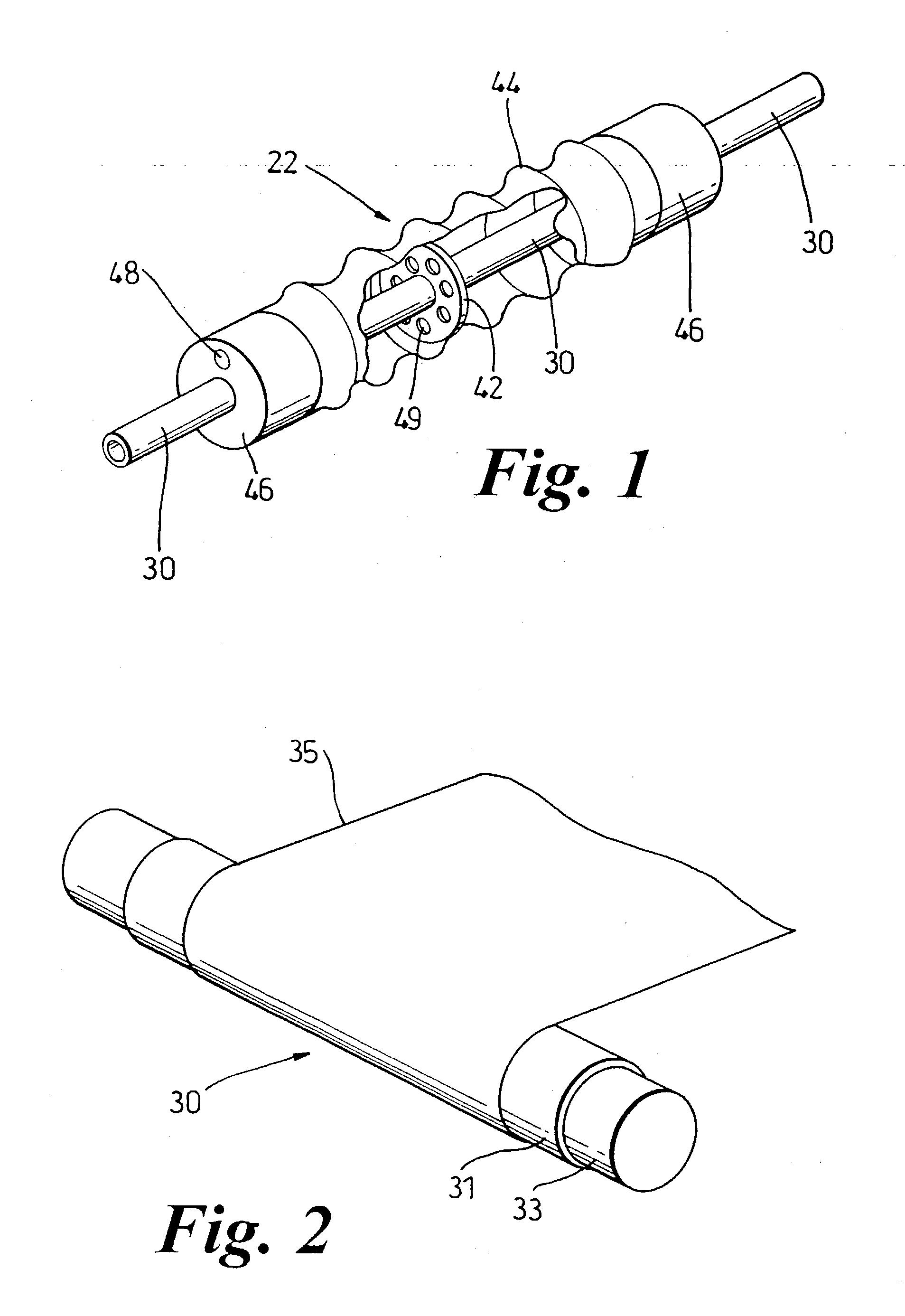
[0079] A thin longitudinally expanded PTFE base tube possessing a wall thickness of 0.131 mm, an inner diameter of 4.0 mm, Gurley number of 0.9 sec, and an IBP of 0.79 psi (0.0055 MPa) is obtained. Referring to FIG. 2, this tube 31 is snugly slipped over 0.180 inch (4.6 mm) diameter mandrel 33.

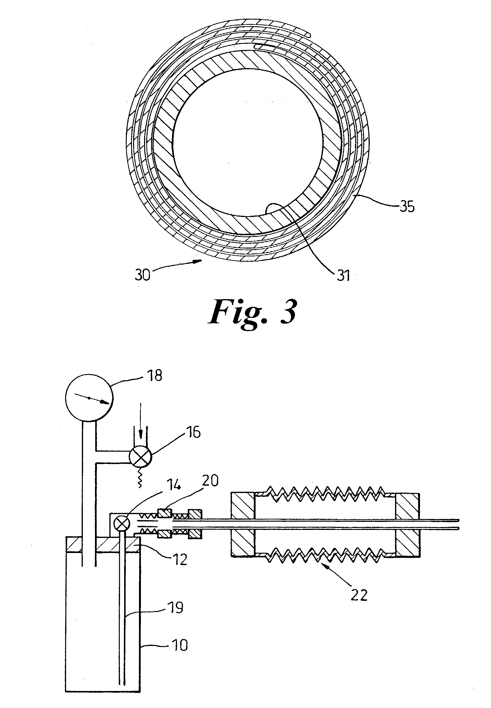
[0080] Expanded PTFE film 35 is obtained possessing a thickness of 0.0034 inch (0.086 mm), a Gurley number of 37.1 seconds, and an isopropanol bubble point of 50.3 psi (0.342 MPa). All measurements are made in accordance with the procedures previously described, unless otherwise indicated. This ePTFE film is then circumferentially wrapped over the thin ePTFE base tube such that the width of the film becomes the length of the resultant tube as depicted in FIG. 2. Twenty layers of film are wrapped around the base tube. The cross-sectional geometry of the layered tube construction 30 is spiral-shaped as indicated in FIG. 3.

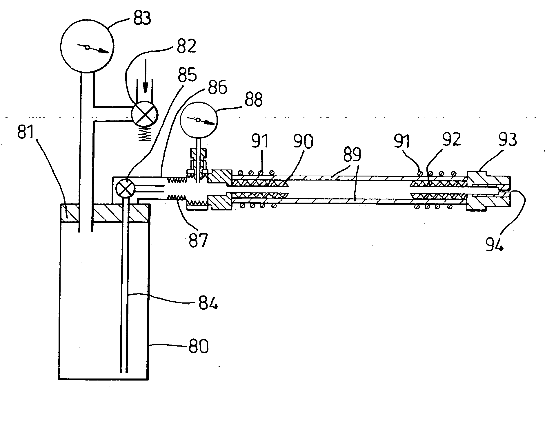
[0081] The ends of the layered film and base tube construction are restrai...


PUM


Abstract

The present invention is an improved tube for the effective transfer of cryogenic fluids and the like. The transfer tube (22) comprises at least two tubes, an inner tube (30) coaxially housed within an outer tube (44) with a defined gap therebetween. The inner tube is sufficiently permeable to gaseous cryogenic fluid that it allows release of limited amounts of gaseous fluid into the defined gap. The outer tube is essentially impermeable so as to contain the gaseous fluid within the gap. Preferably both tubes are constructed from flexible and cold temperature resistant polymer materials, such as fluoropolymer materials and especially expanded polytetrafluoroethylene (PTFE) and / or fluorinated ethylene propylene (FEP). The transfer tube of the present invention is highly effective at cryogenic fluid transfer while being lighter, more flexible, and more efficient than currently available transfer tubes.

Description

[0001] The present invention relates to tubes for transfer of cryogenic fluids, and to containers for storage of cryogenic fluids.DESCRIPTION OF RELATED ART[0002] Vacuum and dry gas insulated tubes are typically used to transport or store cold liquids or liquids with a low heat of vaporisation. The coaxial design of these transfer tubes reduces the warming rate of the cold liquid and results in a reduced exterior temperature. These transfer tubes usually consist of two straight, corrugated or convoluted stainless steel tubes mounted one over top of the other. The use of multiple tubes provides some degree of insulation to help maintain low temperature liquids in a liquid state. The use of corrugations or convolutions lends somewhat increased flexibility (i.e., a reduced bending radius) to the construction. A protective stainless steel mesh is often applied to the outer surface of the transfer tube. Overall, these transfer tubes suffer from numerous problems, including poor bend radi...

Claims


Application Information

Patent Timeline
Patent Type & Authority Applications(United States)
IPC IPC(8): F16L11/12F16L59/14F17D1/04F16L9/18
CPCY02E60/34F16L59/141
Inventor ROBBIE, MARK J.
Owner W L GORE & ASSOCS UK
Why Eureka
Try Eureka