Device for detecting the pmd of optoelectronic transmission lines

a technology of optoelectronic transmission lines and detectors, applied in transmission, transmission monitoring/testing/fault-measurement systems, optical properties testing, etc., can solve the problems of affecting the signal quality, unable to recover digital information,

Inactive Publication Date: 2003-06-12
THORLABS INC
View PDF4 Cites 9 Cited by
  • Summary
  • Abstract
  • Description
  • Claims
  • Application Information

AI Technical Summary

Problems solved by technology

The different propagation velocities of the different spectral portions having different polarization states within the light guide fiber of the transmission link c...

Method used


Image

  • Device for detecting the pmd of optoelectronic transmission lines
  • Device for detecting the pmd of optoelectronic transmission lines
  • Device for detecting the pmd of optoelectronic transmission lines

Examples


Embodiment Construction

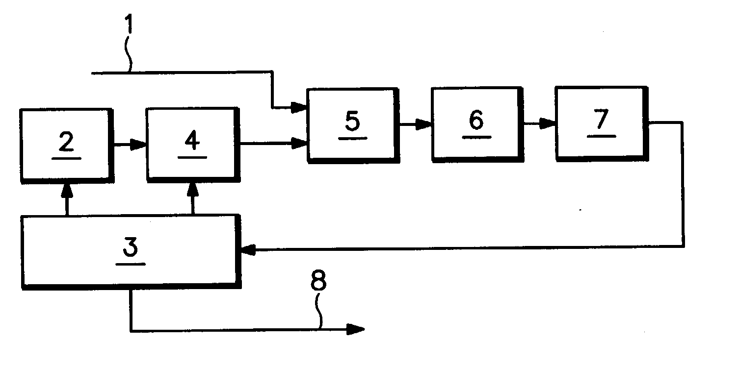
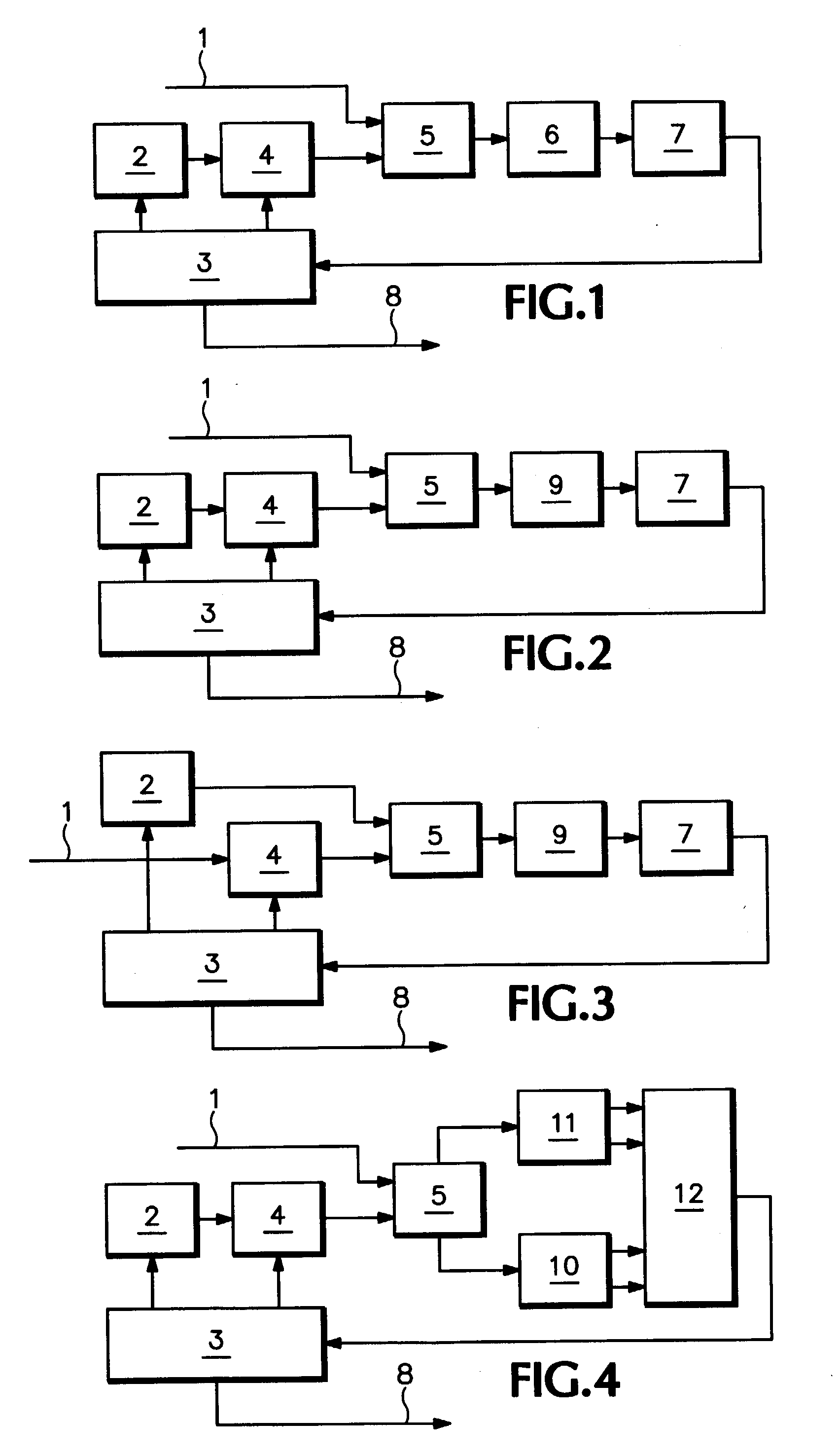
[0069] FIG. 1 schematically shows a first embodiment of a device according to the invention for measuring the PMD, hereinafter also referred to as PMD monitor. A local, tunable laser (2), advantageously an electronically tunable distributed Bragg reflector laser (DBR laser) or an electronically tunable distributed feedback laser (DFB laser), is tuned by a control unit (3) such that the wavelength range of tuning sweeps the spectrum of a signal (1) of a transmission link to be analyzed. The polarization of the local laser (2) is set to the four different polarization states required for determining the PMD by means of a polarization controller (4). In an optical coupler (5) that conveniently is a 3 dB coupler, the signal (1) to be analyzed is added to the radiation of the local laser (2).

[0070] In the succeeding optoelectronic receiver (6), advantageously a photodiode, an electrical superposition signal is generated. A HF filter and evaluation unit (7) limits the bandwidth of the sup...


PUM


Abstract

The invention relates to a device for detecting the PMD of optoelectronic transmission lines. The inventive device is characterized in that it comprises a narrow-band, tuneable laser, whose illumination is superimposed with the illumination of the transmission line to be analysed and an optoelectronic heterodyne receiver which receives the superimposed signal.

Description

[0001] The invention relates to a device for detecting the polarization mode dispersion (hereinafter PMD) of optoelectronic transmission links.PRIOR ART[0002] A known method for determining the distortions caused by polarization mode dispersion (PMD) in optical communication links such as fiber lines, or the effects thereof on the transmission quality of such links, respectively, is the measurement of the bit error rate. This method provides a statement about the effect of the PMD, but no statements about the magnitude of the PMD itself.[0003] Another known method for determining the PMD uses a set of high frequency filters after the optoelectronic detection of the usable signal in order to determine the phase shifts of selected side frequencies. Therein, the effort depends on the modulation bandwidth of the usable signal. Different bit rates in the digital transmission require different filter combinations. Usually, only ca. 3-4 filters are feasible. The determination of the PMD is...

Claims


Application Information

Patent Timeline
IPC IPC(8): G01M11/00G02F2/00H04B10/2569G01M11/02
CPCH04B10/2569G01M11/336
Inventor BANDEMER, ADALBERTKRAUSE, EGBERT
Owner THORLABS INC
Why Eureka
Try Eureka