
Temperature compensation device and electronic apparatus comprising such a device

Inactive Publication Date: 2003-06-19
NXP BV
View PDF4 Cites 11 Cited by
  • Summary
  • Abstract
  • Description
  • Claims
  • Application Information

AI Technical Summary

Benefits of technology

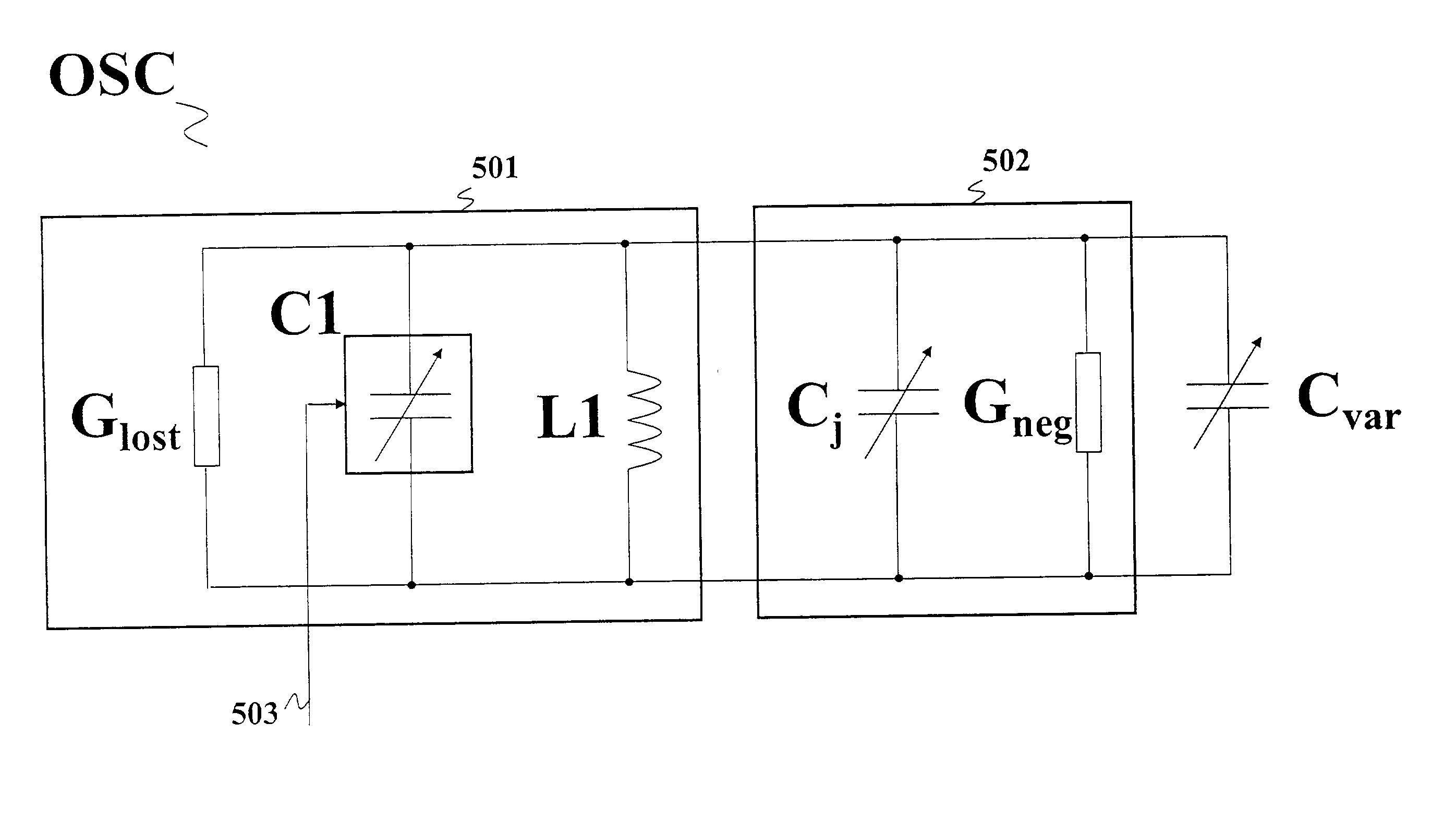
[0012] The variable capacitance is such that its variation compensates the effects of the intrinsic capacitance variation on the operation of the electronic apparatus by cumulation of the capacitive effects of the variable capacitance and the intrinsic capacitance.
[0013] The advantage of such a solution is that it acts directly on the intrinsic capacitance and not indirectly as in the prior-art document, by acting on the bias parameters of the electronic apparatus. Indeed, the compensation device according to the invention does not act on the bias of the components constituting the electronic apparatus. This gives the invention a great flexibility of use to the extent that the compensation device may be easily inserted in an electronic apparatus without modifying the bias parameters. The proposed solution thus prevents any perturbation of the stability of operation of said electronic apparatus, which would be caused by a modification of the bias parameters.
[0020] This solution is also advantageous because the connection of the compensation device with the transistor (whose intrinsic capacitance must be modified) is easy because it consists of a single connection of the reverse-biased junction with said transistor.
[0028] A tuner generally comprises several selective filters for selecting a given channel in a RF input signal and at least an oscillator generating a signal to a mixer for effecting a frequency shift of said channel. In contrast to the filters, the oscillator generally comprises active components of the transistor type for generating a negative conductance with the object of maintaining the oscillations. The frequencies of the selective filters and of the oscillator are adjusted by means of a unique variable control voltage generated by a phase-locked loop (hereinafter denoted by PLL) with which the frequency of the signal generated by the oscillator can be stabilized.
[0031] The use of a compensation device according to the invention in a tuner is particularly advantageous because it allows compensation of the variation of the intrinsic capacitances of said transistors without the control voltage being modified. As the oscillator is thus internally compensated, it avoids the shift of the filters, which leads to a better linearity of operation of the tuner when the temperature varies.

Problems solved by technology

Although it has a low value, this intrinsic capacitance turns out to be detrimental for the operating stability of electronic apparatuses when the temperature develops, particularly in electronic apparatuses comprising resonant circuits.
This causes a variation of the frequency of the signal generated by the resonant circuit when the temperature varies, which involves a frequency drift of the resonant circuit and perturbs the operation of the electronic apparatus.
These compensation means have a certain number of limitations.
Indeed, in so far as the means used in the prior-art document consist of a direct modification of the bias parameters of the oscillator, this solution presents the risk that the oscillation conditions of the oscillator are no longer respected, leading to instabilities of operation of the oscillator, or even to its stopping.
On the other hand, the means used require a difficult regulation of the compensation parameters to the extent that a large number of components is implemented.
Moreover, due to the high number of components used, the solution is costly and difficult to integrate in an integrated circuit.

Method used


Image

  • Temperature compensation device and electronic apparatus comprising such a device
  • Temperature compensation device and electronic apparatus comprising such a device
  • Temperature compensation device and electronic apparatus comprising such a device

Examples


Embodiment Construction

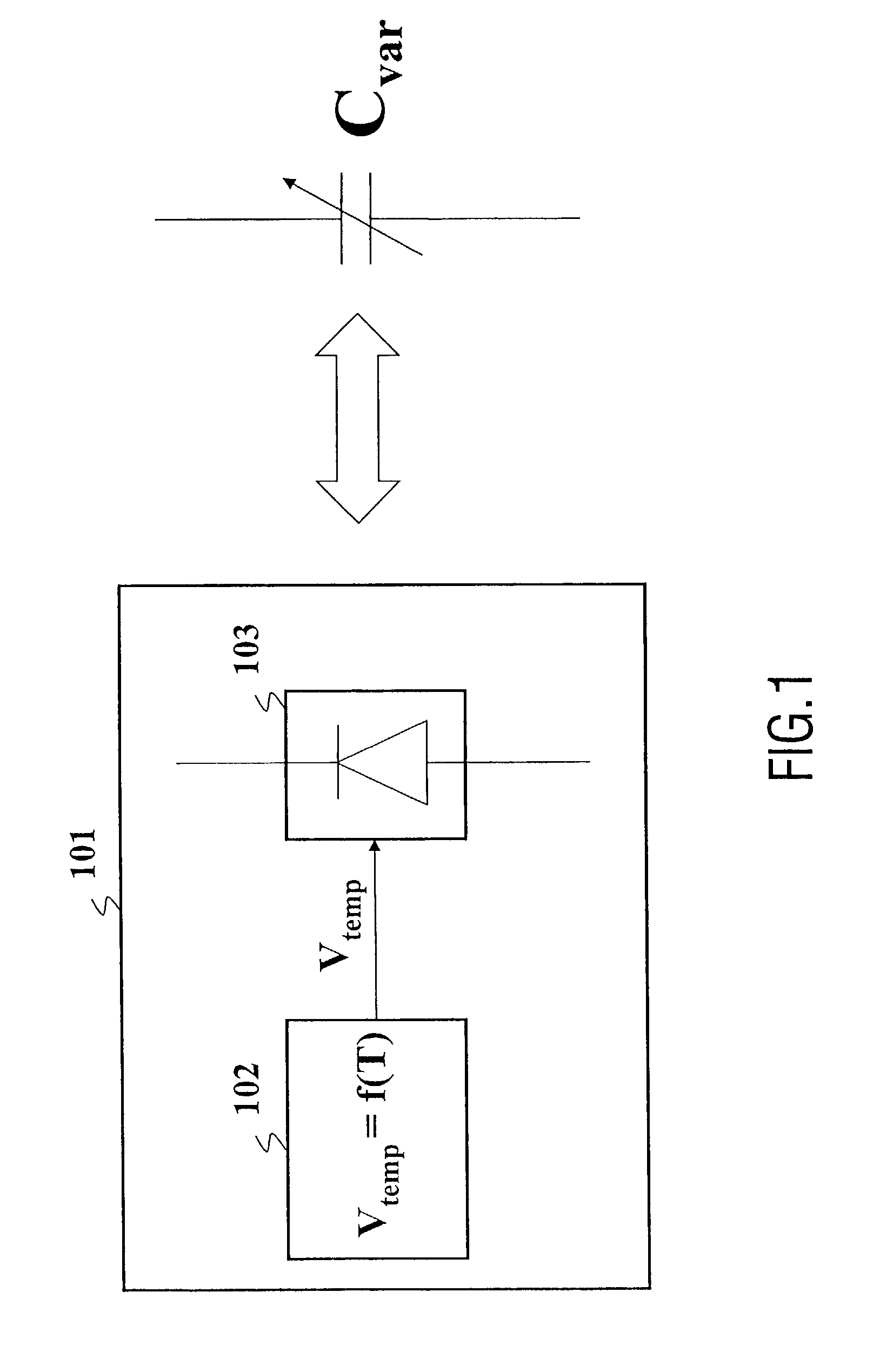
[0043] FIG. 1 illustrates the principle of operation of the compensation device 101 according to the invention.

[0044] The compensation device 101 according to the invention comprises means 102 for generating a bias signal V.sub.temp, and a junction 103 which is reverse-biased by said bias signal. The bias signal V.sub.temp has the characteristic feature of having a variable level when the temperature T varies. The association of the means 102 and 103 is equivalent to a capacitance C.sub.var having a variable value as a function of the temperature.

[0045] When this capacitance C.sub.var is connected to a transistor having an intrinsic capacitance with a variable value as a function of the temperature, it compensates the effect of said intrinsic capacitance.

[0046] The junction 103 may particularly correspond to a diode, for example, a diode of the Schottky type or to a transistor junction.

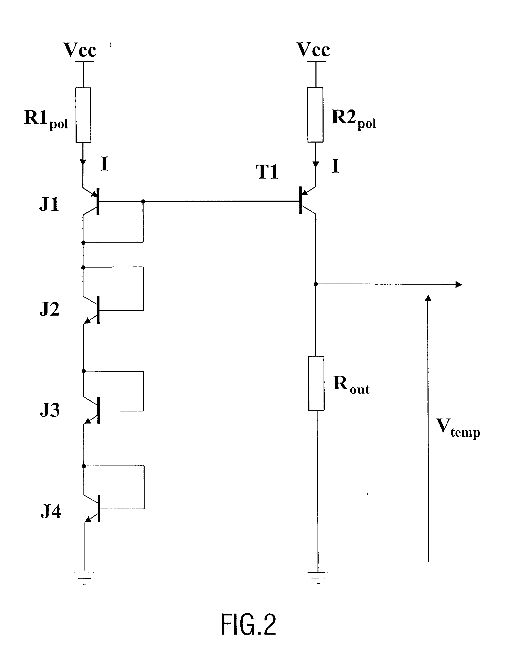
[0047] FIG. 2 shows an embodiment of a circuit with which a bias signal V.sub.temp varying as a fu...


PUM


Abstract

The invention relates to an electronic apparatus comprising at least one transistor having a control terminal and an intrinsic capacitance junction with a variable value as a function of the temperature, said transistor being associated with a compensation device for compensating the effects of the variation of said intrinsic capacitance junction. To this end, the electronic apparatus is characterized in that said compensation device comprises a combination of means behaving as a variable capacitance, said variable capacitance having such a variation as a function of the temperature that it compensates said effects, said variable capacitance being connected to said intrinsic capacitance. The invention is particularly advantageous for compensating the frequency drift of a voltage-controlled oscillator.

Description

[0001] The invention relates to an electronic apparatus comprising at least one transistor having a control terminal and an intrinsic capacitance junction with a variable value as a function of the temperature, said transistor being associated with a compensation device for compensating the effects of the variation of said intrinsic capacitance junction.[0002] The invention notably finds numerous applications in electronic apparatuses comprising resonant circuits.[0003] It is known from the prior art that transistors have several intrinsic capacitance junctions with a variable value as a function of the temperature. Particularly, one of the intrinsic capacitances is connected between the input terminal (referred to as base in a bipolar transistor and as gate in a field effect transistor) and an output terminal of the transistor (referred to as collector in a bipolar transistor and as drain in a field effect transistor). Due to the Miller effect, this intrinsic capacitance has its va...

Claims


Application Information

Patent Timeline
IPC IPC(8): H03B5/04H03F1/30H03L1/02
CPCH03L1/023H03B5/04
Inventor AMIOT, SEBASTIENDULOY, BERTRAND
Owner NXP BV
Learn More