Micromechanical component and corresponing production method

a micromechanical and production method technology, applied in microstructural devices, microstructured technology, fluid pressure measurement, etc., can solve the problems of increased handling and packaging costs, large share of the cost of manufacturing an acceleration sensor by surface micromachining, and increased costs

Inactive Publication Date: 2003-06-26
ROBERT BOSCH GMBH
View PDF4 Cites 46 Cited by
  • Summary
  • Abstract
  • Description
  • Claims
  • Application Information

AI Technical Summary

Problems solved by technology

This results in increased expense for handling and packaging.
This problem may be circumvented by a sensor having the evaluation circuit on a separate chip, e.g., the structures produced by surface micromachining are covered by a second cap wafer.
This type of packaging causes a large share of the cost of manufacturing an acceleration sensor by surface micromachining.
These costs arise as a result of the high surface area requirements of the sealing surface between the cap wafer and the sensor waf

Method used


Image

  • Micromechanical component and corresponing production method
  • Micromechanical component and corresponing production method
  • Micromechanical component and corresponing production method

Examples


first embodiment

[0063] FIGS. 5a,b schematically show a micromechanical component according to the present invention, specifically a cross-sectional view in FIG. 5a and a top view in FIG. 5b.

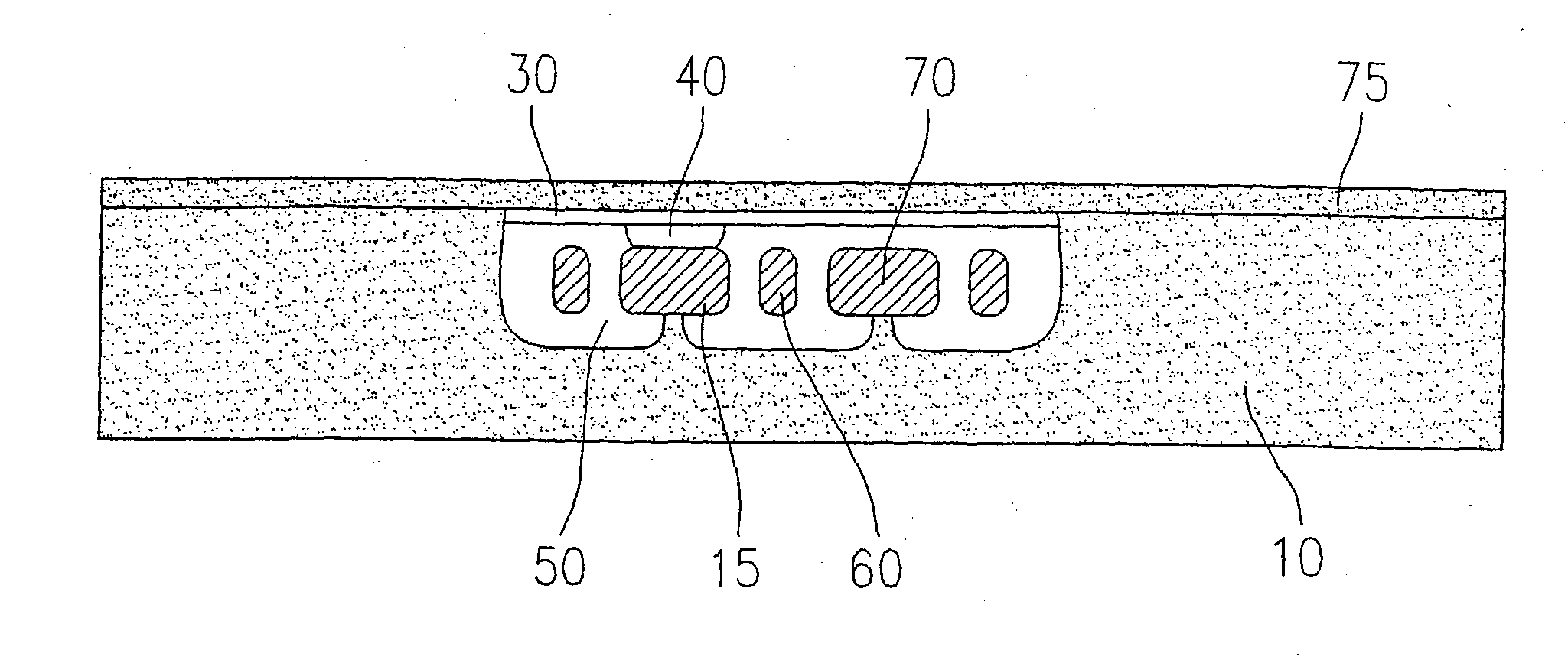
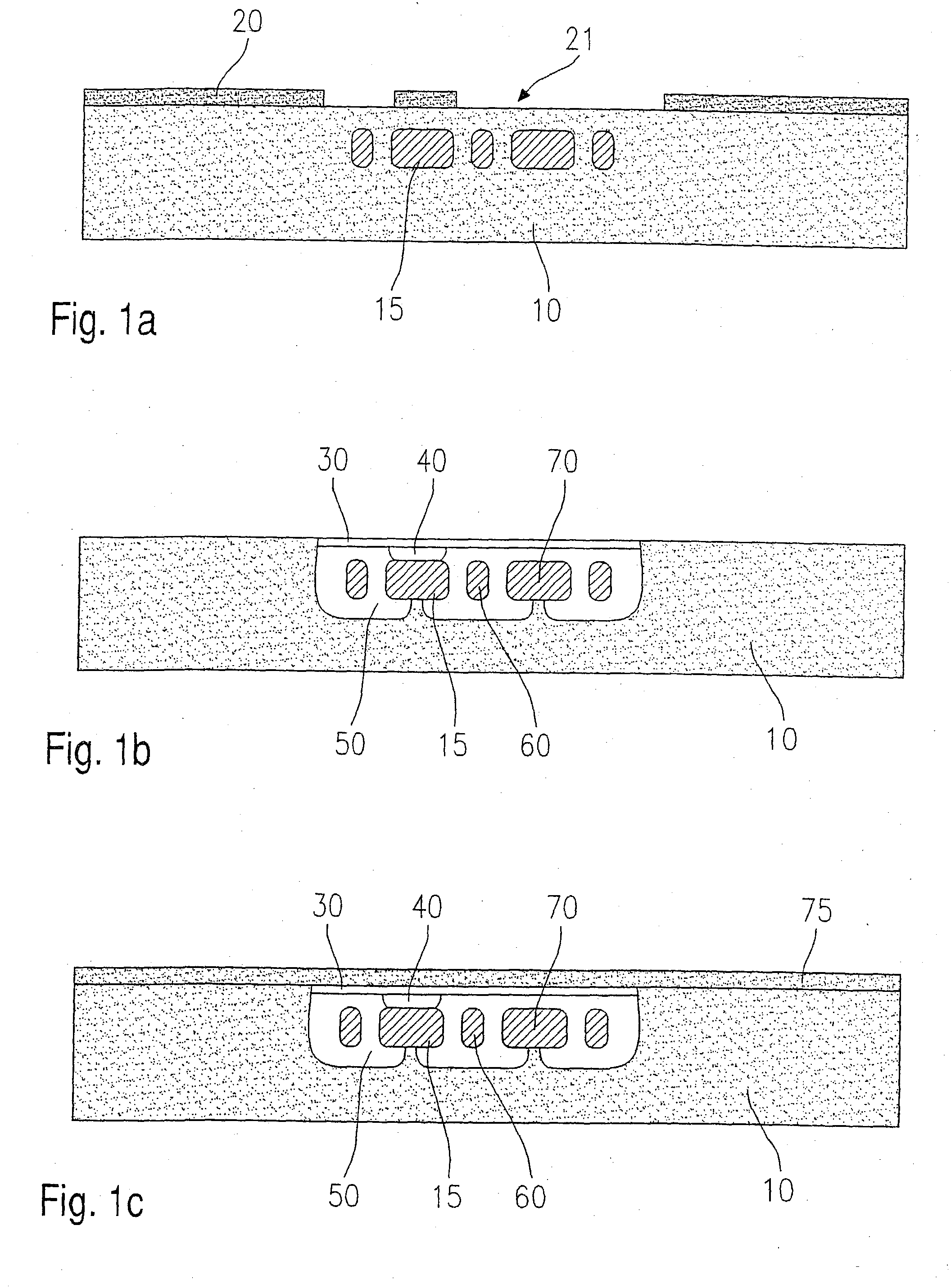
[0064] FIGS. 5a, b illustrate a use as a branched flow channel having defined transfer openings. In this embodiment the transfer openings are provided as back openings 510, while porous zone 30 is hermetically sealed by a sealing layer 75.

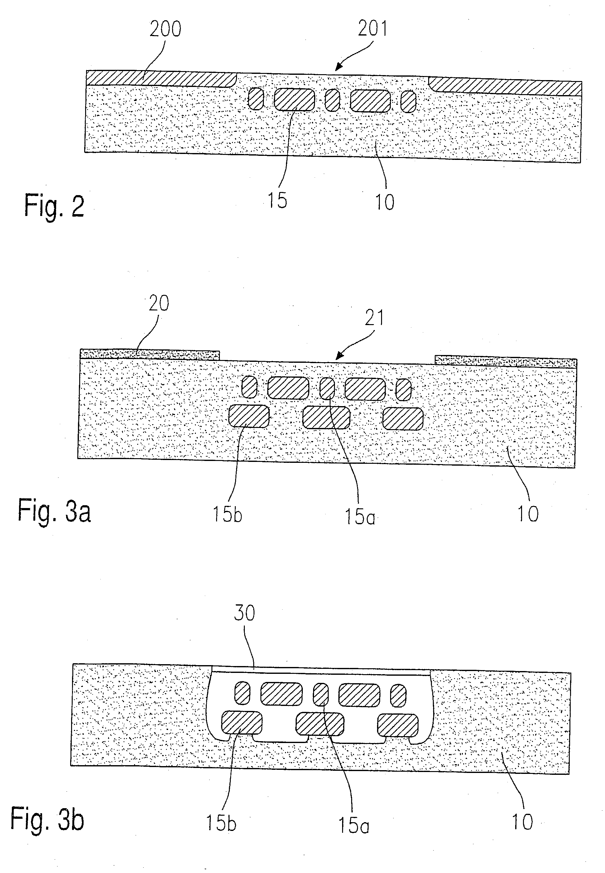
[0065] N-doped zones 15 are used to define the lower limit of cavity 50a and thus the bottom of the flow channel. It is possible to attain the Y-shaped structure of the flow channel by suitable masking.

[0066] In particular, transfer openings 520 are provided in the structure shown in FIGS. 5a, b, which are provided in n-doped zone 15 so that when back openings 510 are etched from the back, the passages do not become too large, which is indicated by the corresponding bell-shaped back etching profile. In this respect, n-doped zone 15 also acts as an etching stop for the etching f...

second embodiment

[0068] FIGS. 6a,b schematically show a micromechanical component according to the present invention, specifically a cross-sectional view in FIG. 6a and a top view in FIG. 6b.

[0069] The structure shown in FIG. 6a is a refinement of the structure shown in FIGS. 5a, b. In this case, piezoresistive resistors 630, 630' are provided on the sealing layer above porous zone 30. Varying flow rates in flow direction FD result in a varying pressure which subjects the diaphragm and thus piezoresistive resistors 630, 630' to a voltage of varying strength. The resulting change in resistance may be analyzed. It is also possible to use a heating structure having temperature sensors analogous to the previous thermal mass flow sensors.

[0070] It is advantageous in this connection that due to the supply of the mass flow from the back, it is not necessary to protect resistance elements 630, 630' against media.

third embodiment

[0071] FIGS. 7a,b show a schematic view in cross-section of a micromechanical component according to the present invention, specifically a micro-sealing ball in FIG. 7a and a micro-sealing plate in FIG. 7b.

[0072] The embodiment shown in FIGS. 7a, b relates to a check valve. In this case, 730 denotes a micro-sealing ball in FIG. 7a and 740 denotes a micro-sealing plate in FIG. 7b, which together with transfer opening 720 in n-doped zone 15b form a check valve. Micro-sealing ball 730 and / or micro-sealing plate 740 are formed simultaneously with the flow channel and / or transfer opening 720 during the anodization process and seal off transfer opening 720 in the event of a return flow.


PUM

PropertyMeasurementUnit
Flow rateaaaaaaaaaa
Structureaaaaaaaaaa
Depthaaaaaaaaaa

Abstract

A micromechanical component having a substrate (10) made from a substrate material having a first doping type (p), a micromechanical functional structure provided in the substrate (10) and a cover layer to at least partially cover the micromechanical functional structure. The micromechanical functional structure has zones (15; 15a; 15b; 15c; 730; 740; 830) made from the substrate material having a second doping type (n), the zones being at least partially surrounded by a cavity (50; 50e-f), and the cover layer has a porous layer (30) made from the substrate material.

Description

BACKGROUND INFORMATION[0001] The present invention relates to a micromechanical component having a substrate made from a substrate material having a first doping, a micromechanical functional structure provided in the substrate and a cover layer to at least partially cover the micromechanical functional structure. The present invention also relates to a corresponding manufacturing method.[0002] Micromechanical function is understood to be any active function, e.g., a sensor function, or passive function, e.g., a printed conductor function.[0003] Although it is applicable to any micromechanical components and structures, in particular to sensors and actuators, the present invention and the underlying problem are elucidated with reference to a micromechanical component, e.g., an acceleration sensor, that is manufacturable using silicon surface micromachining technology.[0004] Monolithically integrated inertial sensors produced by surface micromachining technology in which the sensitiv...

Claims


Application Information

Patent Timeline
IPC IPC(8): G01P15/125B81B3/00B81C1/00H01L29/84
CPCB81B2201/0235B81B2201/036B81C1/00595B81C2203/0136B81C2201/0115B81C2201/0136B81C2201/0114
Inventor BENZEL, HUBERTWEBER, HERIBERTARTMANN, HANSSCHAEFER, FRANK
Owner ROBERT BOSCH GMBH
Why Eureka
Try Eureka