Engine control

a technology of engine control and control system, which is applied in the direction of engine controller, fuel injection control, fuel injection pump, etc., can solve the problems of engine performance reduction, engine performance reduction, and engine temperature adjustment, so as to reduce the performance of the engin

Inactive Publication Date: 2003-07-03
BOMBARDIER RECREATIONAL PROD INC
View PDF4 Cites 10 Cited by
  • Summary
  • Abstract
  • Description
  • Claims
  • Application Information

AI Technical Summary

Benefits of technology

[0011] In view of the foregoing, one aspect of the present invention is to provide an engine control system that increases the temperature of the exhaust gas exiting into an exhaust pipe, during high RPM and low exhaust pipe temperature, without reducing the engine's performance during normal operation.
[0012] Another aspect of the present invention is to provide an engine control system that determines an engine speed and an exhaust gas or exhaust pipe temperature to modify the air / fuel ratio and increase the power output of the engine.
[0022] Another aspect of the present invention is to provide a method of operating an engine including, determining an engine speed, calculating a moving average engine speed, obtaining from the map the duty cycle of a solenoid, and operating the solenoid at the determined duty cycle operation to alter the fuel flow to the engine such that the power output of the engine will be increased.

Problems solved by technology

The temperature, thus the speed of sound, inside the tuned pipe at the beginning of a race is not aligned with the optimal operating characteristics of the engine at operating speed.
Therefore, when the operator wishes to increases the speed of the vehicle by increasing engine RPM, the tuned pipe is un-tuned with respect to the exhaust pipe temperature, and the engine will not produce maximum power output until the temperature increases to that which the tuned pipe is tuned.
Retarding the ignition by igniting the fuel mixture after its optimal ignition point causes a reduction in the thermal efficiency, producing a higher exhaust gas temperature.
Although this procedure results in a higher exhaust gas temperature during early engine operation, thus increasing the speed of sound in the tuned pipe, it requires the engine to operate at non-optimal operating conditions during the normal course of the engine operation once the exhaust gas temperature in the tuned pipe has reached a maximum.

Method used


Image

  • Engine control
  • Engine control
  • Engine control

Examples


Embodiment Construction

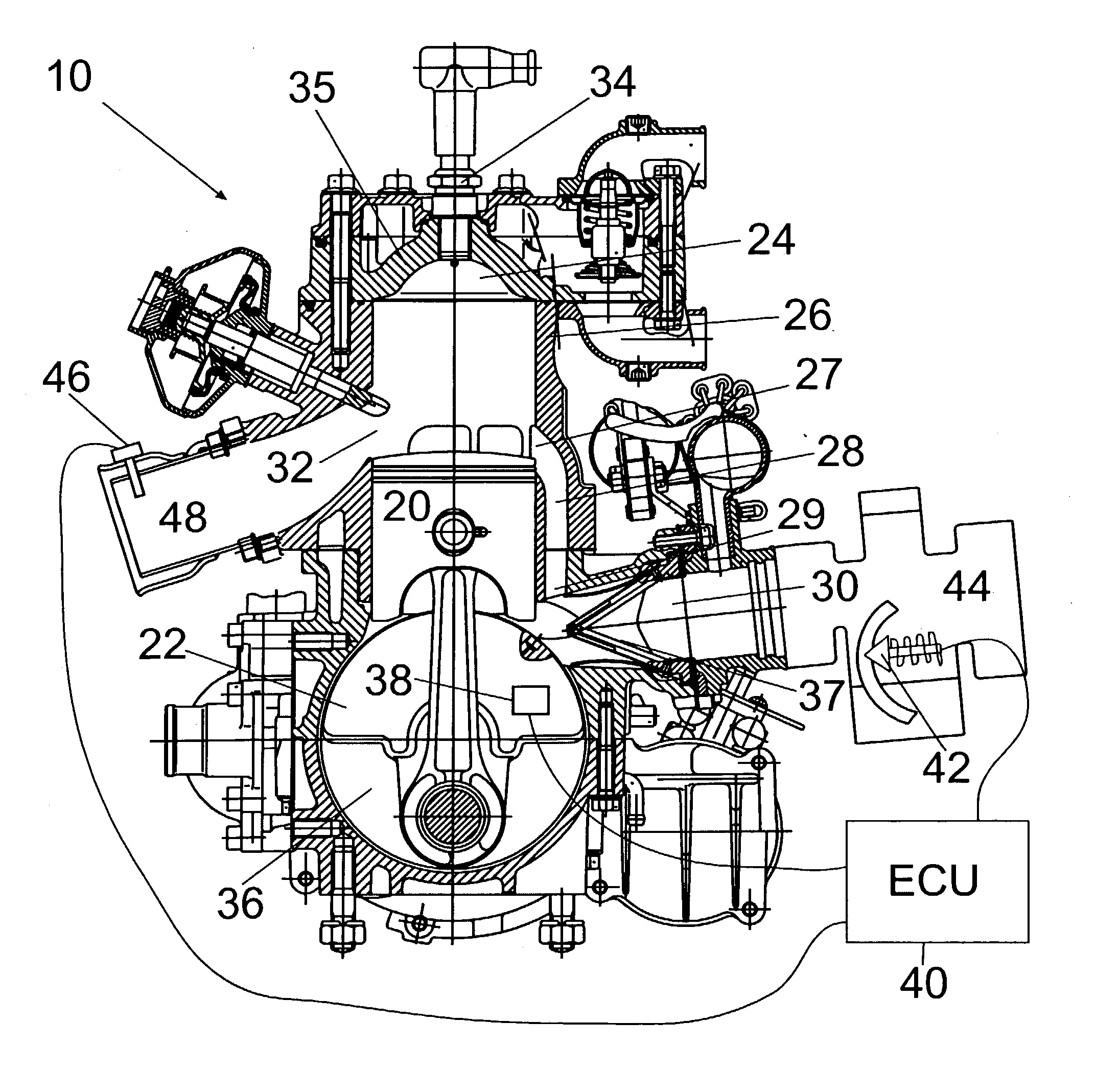
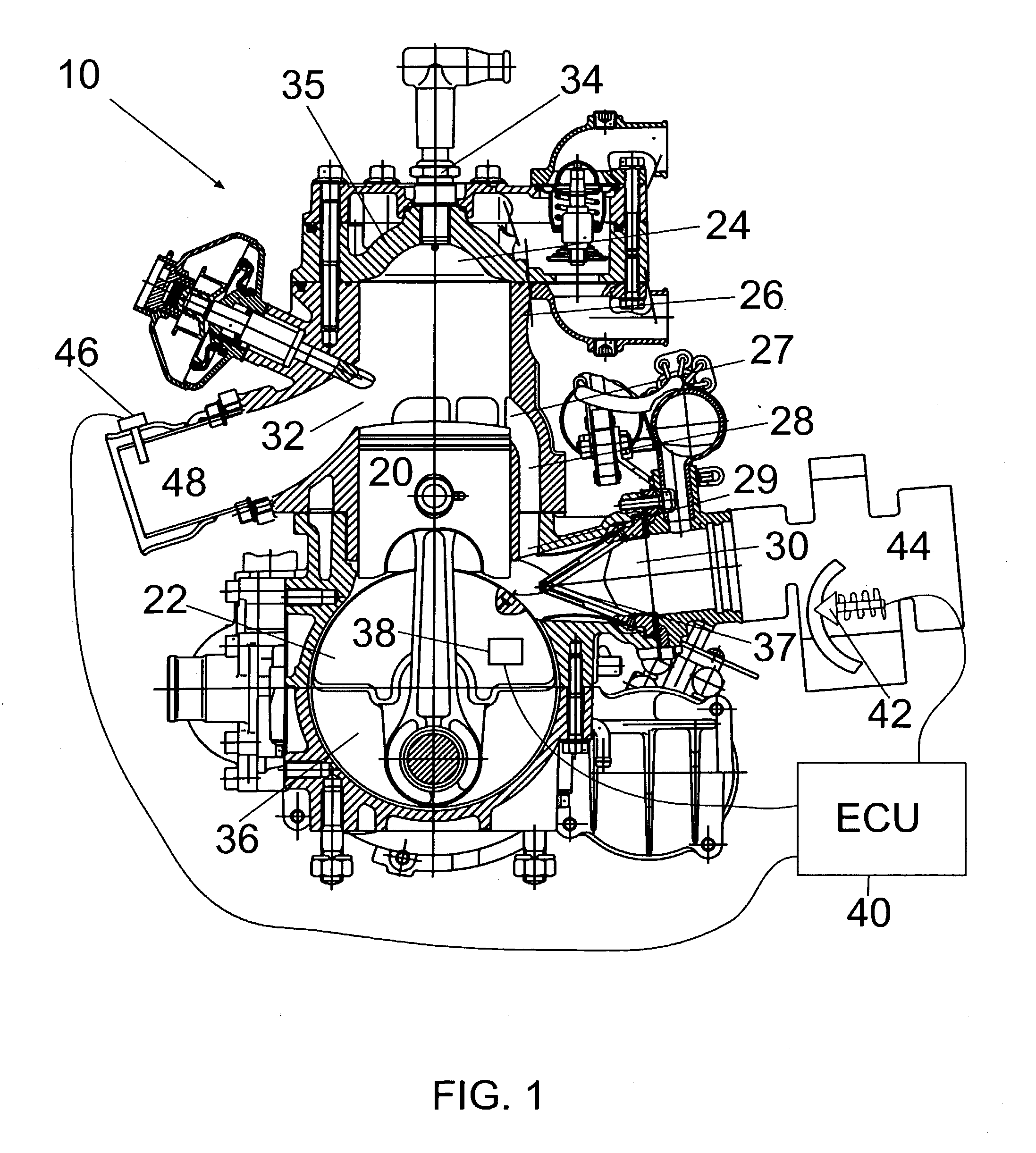
[0031] Referring to FIG. 1, a two-stroke engine 10 includes a piston 20 connected to a crankshaft 22. Piston 20 reciprocates inside a cylinder wall 26 of the engine 10. A cylinder 24 is formed between the cylinder wall 26 and the cylinder head 35. A transfer port 28, connecting the cylinder 24 to the crankcase 36, passes through the cylinder wall 26. The transfer port 28 has a first opening 27 in the cylinder 24 and a second opening 29 in the crankcase 36. The cylinder wall 26 also has an opening 32 to the atmosphere forming the exhaust port of the engine 10. An air / fuel inlet 30 enters into the crankcase chamber 36 passing through a reed valve 37 wherein the air / fuel mixture is drawn into the chamber 36 by the vacuum created in the chamber 36 when the piston 20 is traveling upward toward the spark plug 34 (or, alternatively, a plurality of spark plugs). The reed valve 37 prevents the air / fuel mixture from exiting the crankcase chamber 36 while the piston 20 is traveling away from t...


PUM


Abstract

An engine control system utilizes the brake specific fuel consumption (BSFC) to increase the temperature of the exhaust gas present in the exhaust pipe and determines a moving average engine speed from at least two actual engine speeds determined from a speed sensor located on the crankshaft of the engine. The control system also includes a map that uses the moving average engine speed and the actual engine speed to retrieve a solenoid duty cycle to alter the BSFC of the engine at certain RPM to increase the maximum power output of the engine.

Description

[0001] This application claims the benefit of priority to U.S. application Ser. No. 60 / 344,052, filed Jan. 3, 2002, the contents of which are herein incorporated by reference.[0002] The present invention relates to an engine control system that enables an engine to obtain an increased power output during high RPM and low exhaust pipe temperature operation by modifying the brake specific fuel consumption (BSFC) of the engine.[0003] Maximum power output of an engine can be achieved by determining the optimal operation of several different engine parameters. For example, maximum power output of an engine could be obtained by determining the optimal ignition angle for a specific air / fuel ratio and a specific fuel octane level at a specific exhaust temperature found in the exhaust pipe of the engine. Operation of the engine at these parameters will produce the maximum power output as long as any one of the parameters does not change. As the engine runs and the temperature in the exhaust ...

Claims


Application Information

Patent Timeline
Patent Type & Authority Applications(United States)
IPC IPC(8): F02B15/00F02B75/02F02D31/00F02D41/02F02D41/08F02D41/24
CPCF02B2075/025F02D31/007F02D41/0245F02D41/0255Y02T10/26F02D41/2496F02D2041/026F02D2041/2027F02D2400/04F02D41/083Y02T10/12
Inventor MATTE, SYLVAIN
Owner BOMBARDIER RECREATIONAL PROD INC
Why Eureka
Try Eureka