
Method of preparing membrane-electrode-gasket assemblies for polymer electrolyte fuel cells

Inactive Publication Date: 2003-07-03
HYUNDAI MOTOR CO LTD
View PDF9 Cites 33 Cited by
  • Summary
  • Abstract
  • Description
  • Claims
  • Application Information

AI Technical Summary

Benefits of technology

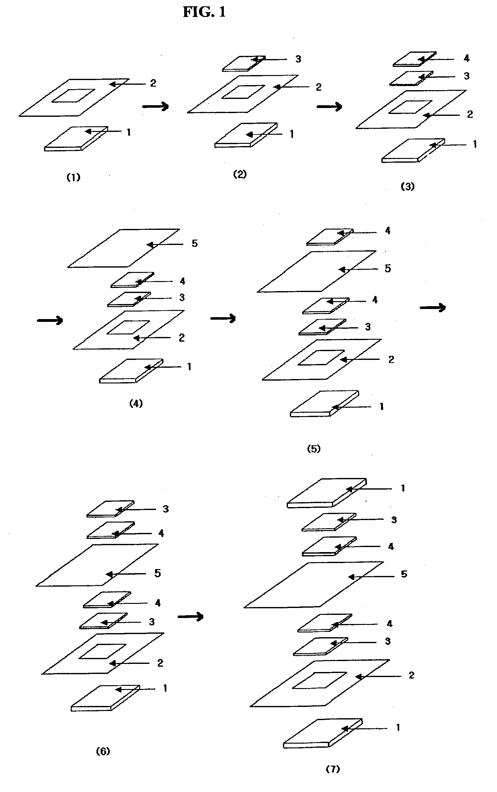
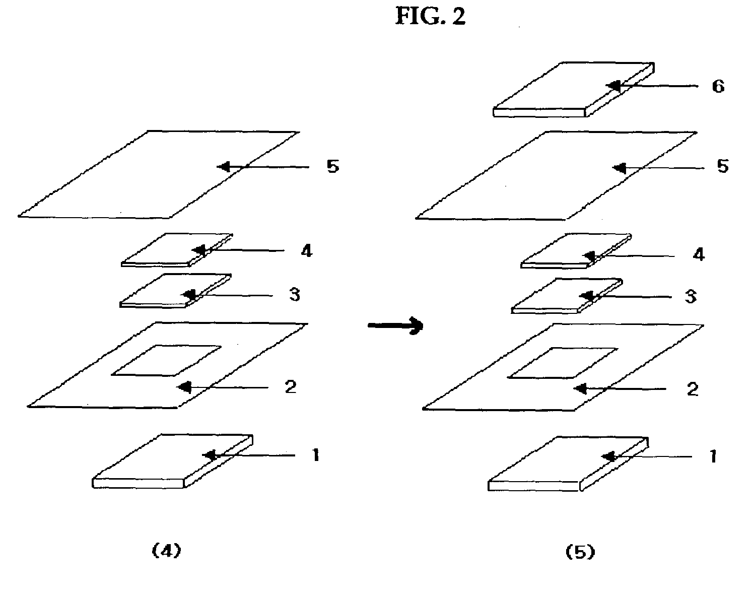
[0008] A typical PEFC is constructed by assembling separate components including membrane-electrode assembly (MEA), gaskets, and separators. According to the invented method, PEFC is fabricated by assembling separators and MEGA, into which MEA and at least one gasket are integrated. Compared to the conventional MEA-gasket assemblies, MEGAs are easier to handle, easier to install, and can be more readily mass-produced via a manufacturing process in a series. Moreover, employing MEGAs improves PEFC performance since the manufacturing process allows the membrane thickness of MEGAs to be lower than that of the conventional MEA-gasket assemblies.

Problems solved by technology

To construct PEFCs using MEAs prepared by the above-mentioned methods, gaskets are inserted between MEAs and separators to obtain gas tightness, which makes manufacturing process of the fuel cells complicated and adds an additional step wherein the extensively pre-fabricated subassembly can be damaged.
Additionally, the relatively low ionic conductivity of the Nafion membrane is one of the major sources to reduce the cell efficiency.
Finally, the fabrication processes described therein are cumbersome and not readily amenable to mass production.
Pore blocking results from penetration of ionomer into the catalyst pores, and this decreases fuel cell efficiency.
On the other hand, the tape-casting of Nafion solution can possibly decrease the fuel cell efficiency due to penetration of Nafion solution into the pores of the electrode catalyst layers.
As a result, this improvement can not only increase efficiency of fuel cells but also be profitable in operation cost.

Method used


Image

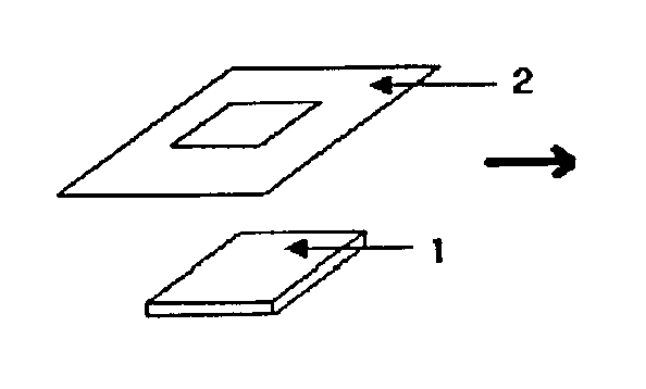
  • Method of preparing membrane-electrode-gasket assemblies for polymer electrolyte fuel cells
  • Method of preparing membrane-electrode-gasket assemblies for polymer electrolyte fuel cells
  • Method of preparing membrane-electrode-gasket assemblies for polymer electrolyte fuel cells

Examples


example 2

[0053] A MEGA having anode and cathode with 0.4 mg / cm.sup.2 and 0.7 mg / cm.sup.2 of Pt, respectively, were prepared by the same method as mentioned in Example 1. To prevent Nafion solution from penetrating into pores of the electrode catalyst layer during the formation of Nafion layer on the electrode, 20 wt % of Nafion solution was tape-cast on an inert polymer film using a doctor blade and dried up for 5 min. Then the prepared electrode (0.7 mg / cm.sup.2) was put on the Nafion solution and left at room temperature for drying. After formation of Nafion layer on the cathode, Teflon gasket was attached to the margin of Nafion membrane by the same method as in Example 1. MEGA was prepared by attaching the anode to the Nafion membrane.

[0054] The efficiency of the MEGA was measured at an operating temperature of 80.degree. C. under a pressure of 1 atm using hydrogen and oxygen as reactant gases, and the result is shown in FIG. 4. As shown in FIG. 4, MEGA in Example 2 exhibited a good cell...


PUM

PropertyMeasurementUnit
Linear densityaaaaaaaaaa

Abstract

A manufacturing method of Membrane-Electrode-Gasket Assemblies (MEGAs) used for polymer electrolyte fuel cells (PEFCs) is described wherein a polymer electrolyte membrane is formed directly on a electrode. A typical PEFC is constructed by assembling membrane-electrode assembly (MEA), gaskets, and separators. According to the invented method, PEFC is fabricated by assembling separators and MEGA, into which MEA and a gasket are integrated. Compared to the conventional MEA-gasket assemblies, MEGAs are easy to handle and can be mass-produced via a manufacturing process in a series. Moreover, employing MEGAs improves PEFC performance since the membrane thickness of MEGAs is lower than that of the conventional MEA-gasket assemblies.

Description

[0001] The present invention is concerned with a method of manufacturing Membrane-Electrode-Gasket Assemblies (MEGAs), in which a Membrane-Electrode-Assembly (MEA) and a gasket are integrated, used for polymer electrolyte fuel cells (PEFCs). The invention also relates to a method of forming a very thin polymer electrolyte membrane sandwiched between two electrodes.DESCRIPTION OF THE PRIOR ART[0002] Polymer electrolyte fuel cell (PEFC) is an energy conversion device which converts chemical energy into electrical energy by the electrochemical reactions of hydrogen-containing fuels, for example hydrogen or methanol, and oxygen-containing gases, for example oxygen. PEFCs are often subclassified into Solid Polymer Electrolyte Fuel Cell (SPEFC) and Direct Methanol Fuel Cell (DMFC). Performance of PEFCs primarily depends the characteristics of MEAs, which in turn depends on a variety of physical characteristics of the MEAs and, in a related sense, also on the manufacturing process.[0003] V...

Claims


Application Information

Patent Timeline
IPC IPC(8): H01M4/88H01M4/92H01M8/02H01M8/10
CPCH01M4/881H01M4/8828H01M8/0234H01M8/0245H01M8/0273H01M8/0284Y02E60/50H01M8/1011H01M8/1023H01M8/1039H01M8/1081Y02E60/523H01M8/0286Y02P70/50H01M4/88H01M8/02
Inventor OH, IN-WHANHA, HEUNG YONGHONG, SEONG-AHNAHN, SANG-YEOULLEE, YONG-CHULLIM, TAE WONLEE, KICHUNKIM, SOO WHANLEE, JONG HYUN
Owner HYUNDAI MOTOR CO LTD
Learn More