Improved Class BD Amplifier

a technology of amplifiers and amplifiers, applied in the field of electromechanical devices, can solve the problems of increasing reducing the efficiency of class a and ab amplifiers, and requiring significant heat sinking and sometimes forced air cooling, so as to parts, reduce the cost of components, and eliminate to the first order any distortion

Inactive Publication Date: 2003-07-03
ZEFF ROBERT TERRY
View PDF0 Cites 38 Cited by
  • Summary
  • Abstract
  • Description
  • Claims
  • Application Information

AI Technical Summary

Benefits of technology

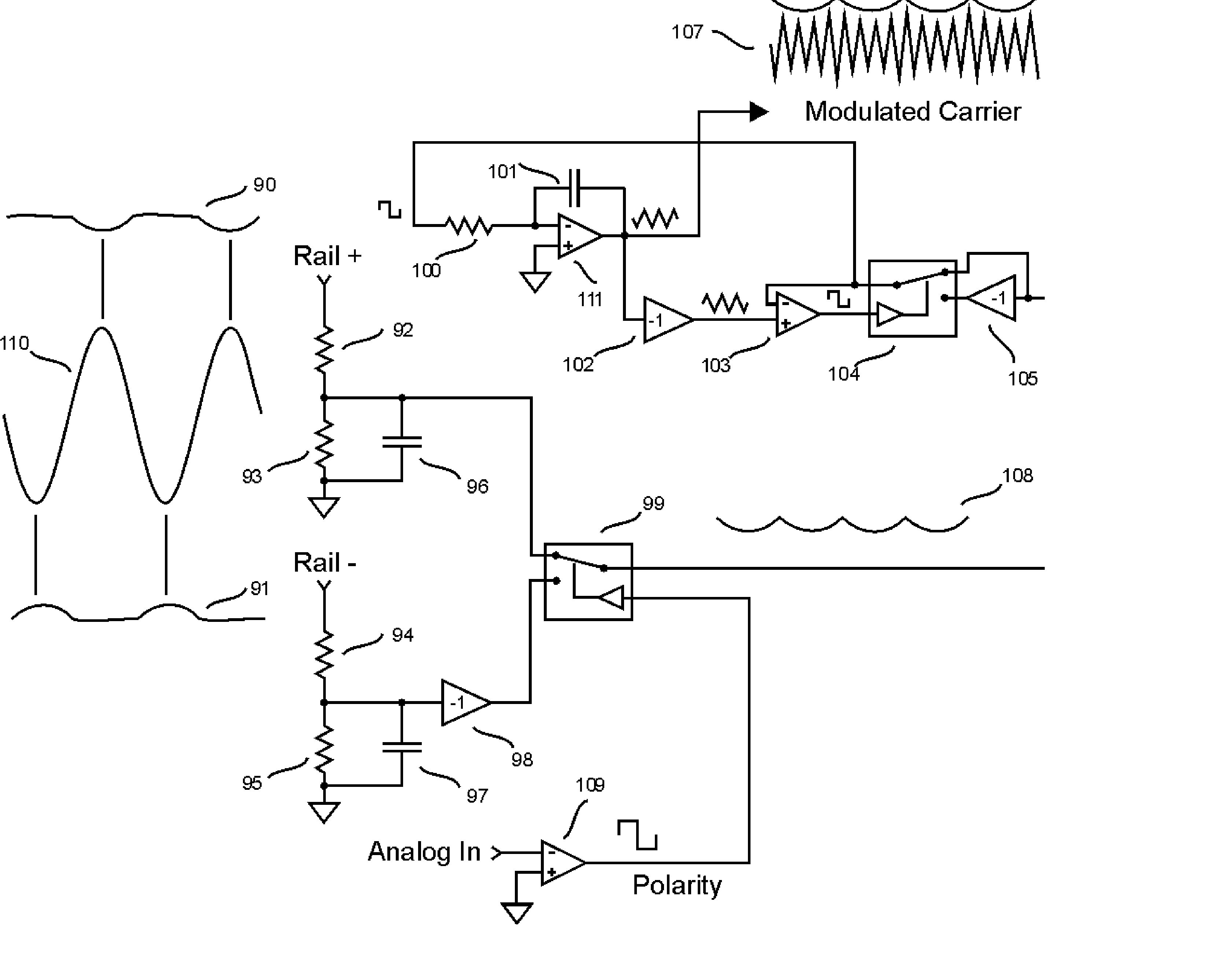
[0031] In one aspect, the present invention provides a reduced component count and parts cost by using an innovative switching topology
[0032] In a second aspect, the present invention provides improved linearity for small signals, by providing an innovative topology where at zero output, small positive and negative pulses are both present on the output of the modulator, thus allowing for linear amplification of signals down to the zero level.
[0033] In a third aspect, the present invention eliminates to first order any distortion on the output from supply voltage variation, by making a symmetrical reference triangle wave of a class BD amplifier be proportional to the supply voltage.

Problems solved by technology

In practice, many class AB amplifiers show some distortion in the output waveform when the output voltage transitions rapidly from one polarity to the other, because it takes some time to turn on the conduction block which has been off in the opposite polarity.
Class A and AB amplifiers are thus very far from being efficient, and can require significant heat sinking and sometimes forced-air cooling for high-power designs.
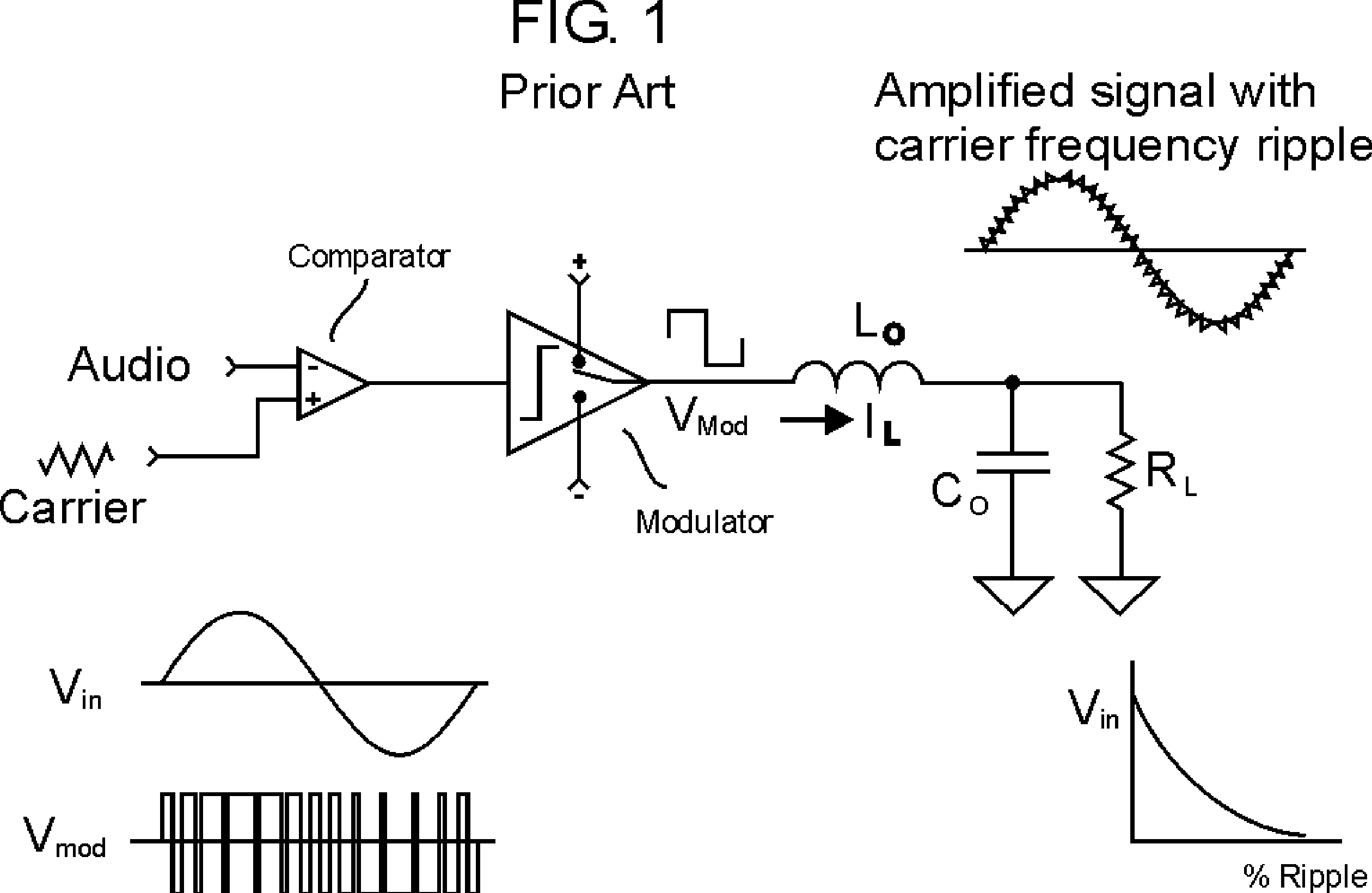
One major disadvantage is a phenomenon commonly referred to in the art as "supply pumping".
Since power supplies are typically designed to source power but not sink power, the supply pumping phenomenon places a limit on how low a frequency input the amplifier can handle without creating an over-voltage condition on the output capacitors of its own power supplies.
The supply pumping problem also causes an output distortion problem, because in the absence of strong negative feedback (which is impractical to employ in switching amplifiers), any change in levels of the supplies causes a change in level of the output, so the output waveform itself becomes distorted from supply pumping.
Unfortunately, in a class D amplifier, negative feedback around the entire amplifier is not practical for two reasons.
The first reason is that the output LC filter creates so much phase shift that the feedback would not be stable.
The second reason is that the large ripple at the modulation frequency causes problems in the feedback.
The disadvantage of adding the balancing choke circuit is that it increases component count, cost, and power dissipation.
The bridged class D amplifier of figure 2 does not have the supply pumping problem of the non-bridged topology of figure 1, and it has the added advantage that it offers twice the peak output voltage to the load, however, it requires twice the number of power-switching components, and it has the additional disadvantage that both sides of its output are driven, so neither side may be connected to ground.
Both bridged and non-bridged class D amplifiers have the problem that as the signal level approaches zero, the ripple on the output approaches a maximum.
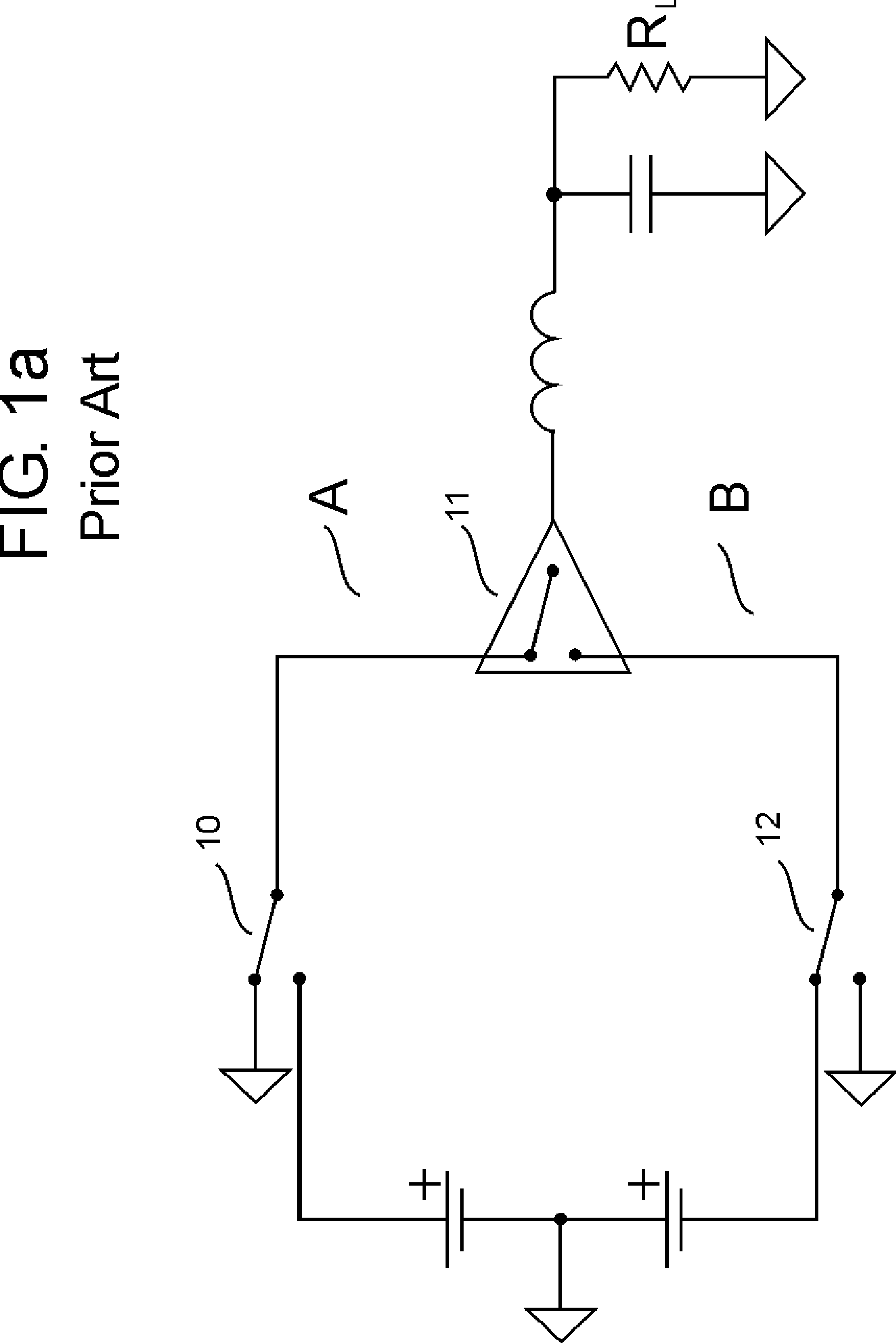
Passing the output current through three switches for each state increases complexity and reduces efficiency.
While an idealized power supply might be thought of as "floating", real-life power supplies always have some stray capacitance from primary to secondary, so switching a power supply about ground at high frequency can cause serious problems.
This high frequency signal will cause serious EMI problems and would require complex filtering.
The output current passes through two switches at all times. Because this design requires bridging, the user of this amplifier does not have the flexibility of further bridging for high power mono output.
Another disadvantage is that bridged designs preclude configurations where one output is ground.
One disadvantage (touched on earlier) of class D and BD amplifier designs known in the art is that any variation in supply voltage causes distortion in the output waveform.
Thus noise and ripple on the supply rails cause distortion.
Also, an imbalance between the positive and negative rails causes distortion because of unsymmetrical gains for the positive and negative output swings.
Unfortunately, the circuitry disclosed in U.S. Pat. #6,356,151 specifically requires a saw-tooth waveform to implement this proportionality.
Besides supply-variation-induced distortion, another disadvantage of class BD amplifiers known in the art is that they have linearity problems for very small input signals.

Method used


Image

  • Improved Class BD Amplifier
  • Improved Class BD Amplifier
  • Improved Class BD Amplifier

Examples


Embodiment Construction

[0053] The current invention improves the prior art Class BD related to:

[0054] 1. The Class BD output stage

[0055] 2. Distortion introduced by supply ripple and noise

[0056] 3. Notch Distortion

[0057] Improved Class BD output stage:

[0058] In prior art for Class BD, the output inductor current is passed through at least two switching devices. In this design, current is passed through a single switching device, except in the low power ground state. In the ground state, current is passed through two switching devices in series. (See FIG. 16) The three states are as follows:

1State SW1 (54) SW2 (52) SW3 (53) SW4 (55) POS ON OFF ON OFF GROUND OFF ON ON OFF NEG OFF ON OFF ON

[0059] In the positive state SW3 (53) could be either on or off, likewise in the negative state SW2 (52) could be on or off. The combination illustrated above simplifies the drive circuitry, requiring just an inverter to drive each grounding state as in FIG 10. The advantage of this design is that in the positive or negati...


PUM


Abstract

Abstract of Disclosure An improved class BD (3-state) switching amplifier is provided requiring fewer power switching devices, and providing improved immunity to power-supply-induced distortion and greatly reduced notch distortion. Asymmetric gate drive delay circuitry produces time-coincident very short positive and negative drive pulses for very small signals, enabling linear performance down to zero input. The reference triangle wave is generated such that the positive amplitude of the triangle wave is modulated by the positive supply and the negative amplitude is modulated by the negative supply, eliminating to first order any supply-induced output distortion.

Description

Background of Invention[0001] This invention relates to the field of electronics, and in more specifically to audio amplifiers and class D and BD amplifiers.[0002] Electronic amplifiers are important building blocks for nearly every piece of consumer and military electronic equipment. Electronic amplifiers are key components of everything from home stereo equipment, to radios & televisions & VCRs, to personal computers & printers, to telephones. Important figures of merit for amplifiers in different applications include cost of implementation, efficiency, size, maximum power output, signal-to-noise ratio, radiated and conducted electromagnetic interference (EMI), linearity, maximum voltage or current output, and bandwidth. Among the applications for amplifiers in consumer electronics, audio amplifiers present some of the strictest demands in terms of signal-to-noise ratio, linearity, and power output. Along with high power output, efficiency also becomes important in audio amplifier...

Claims


Application Information

Patent Timeline
Patent Type & Authority Applications(United States)
IPC IPC(8): H03F3/217H03F3/38
CPCH03F3/217H03F3/38H03F3/2173
Inventor ZEFF , ROBERT TERRY
Owner ZEFF ROBERT TERRY
Why Eureka
Try Eureka