This helps you quickly interpret patents by identifying the three key elements:
Problems solved by technology
Method used
Benefits of technology
Benefits of technology
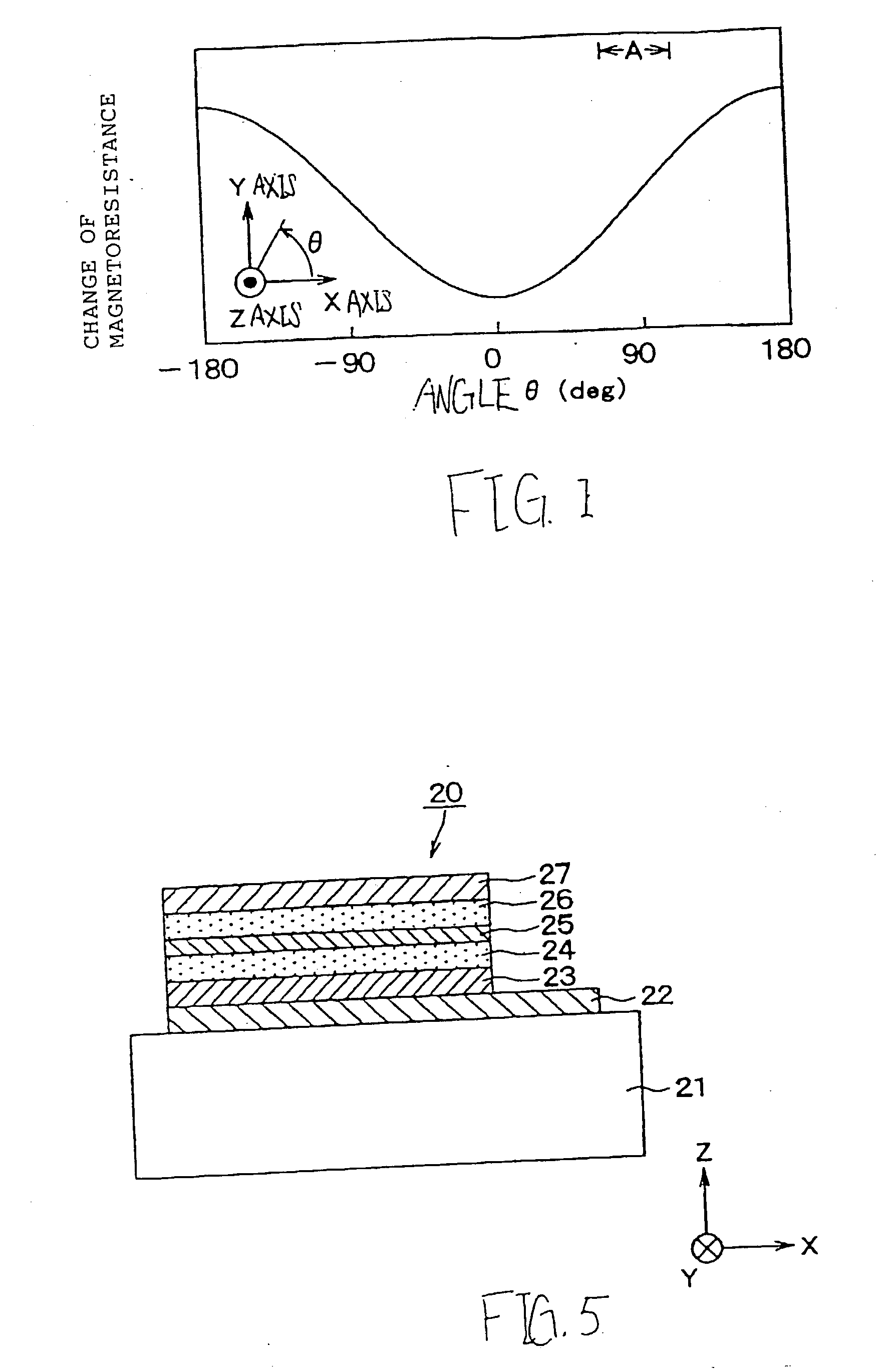
[0019] In FIG. 1, using a range of region A in which the magnetoresistance rapidly changes allows grate change of the magnetoresistance to be detected. That is, it is possible to detect the change of magnetoresistance at high sensitivity when the magnetic field pivotally changes with respect to the Y axis in parallel to the X-Y plane.
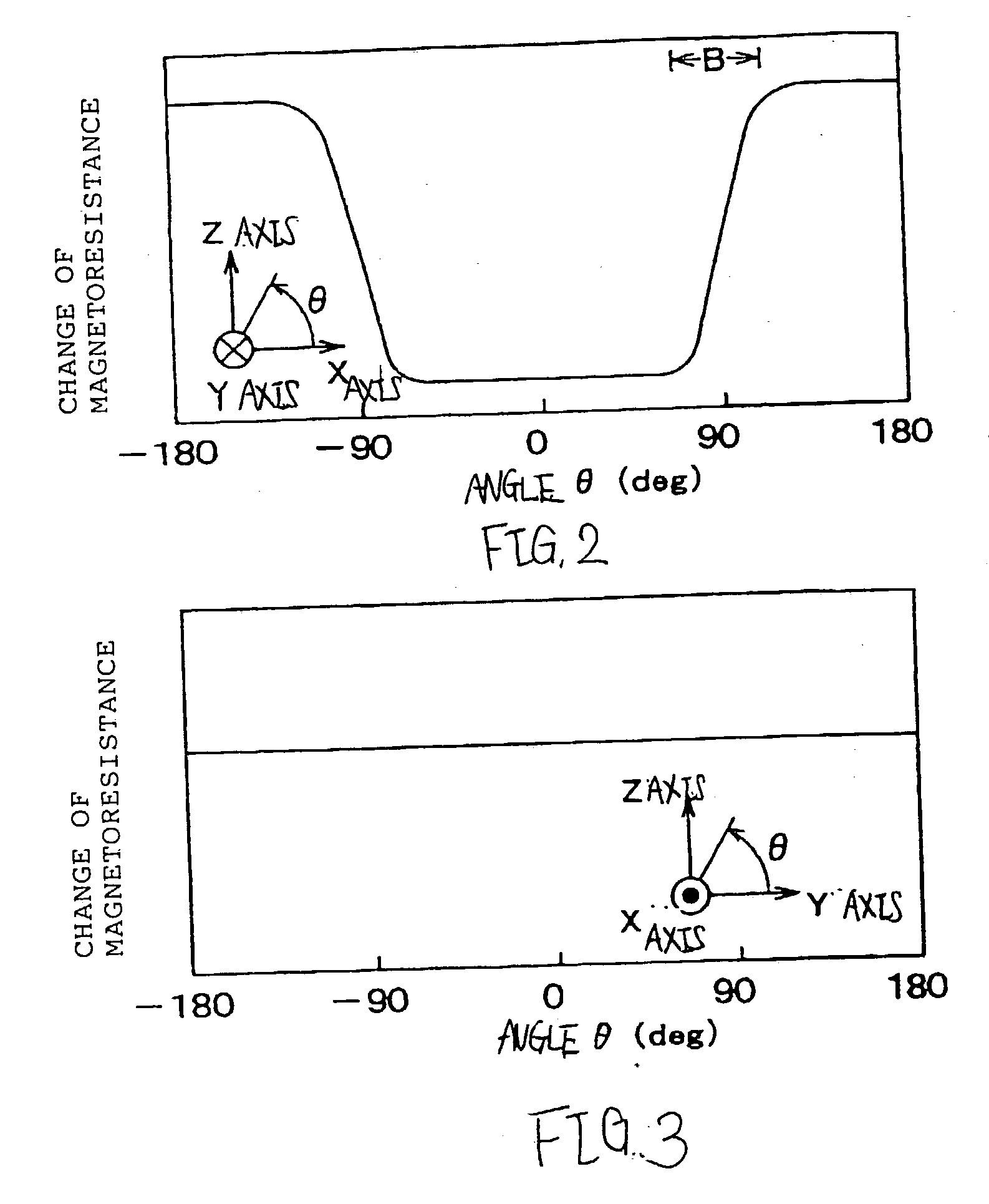
[0048] That is, in the still further aspect of the invention, using the range of region B shown in FIG. 2 in which the magnetoresistance rapidly changes allows the magnetoresistance to be detected at high sensitivity so that it is possible to provide the revolution detecting device having the TMR sensor with a high MR ratio and capable of efficiently detecting the change of sensitivity of the TMR sensor.
Problems solved by technology
Due to the large gain of the amplifier, error component included in the detection signals are large so that an error correction circuit with large-scale must be required for correcting the error component included in the detection signals of the MR element.
Method used
Image
Click on the blue label to locate the original text in one second.
Reading with bidirectional positioning of images and text.
Examples
first embodiment
[0064] (First embodiment)
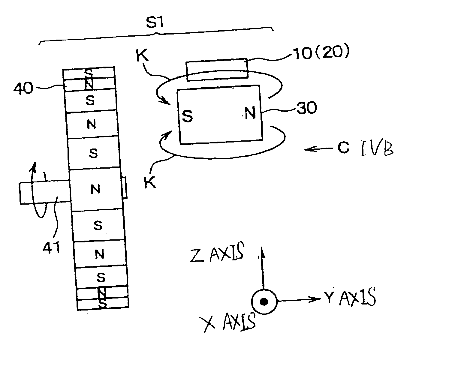
[0065] FIG. 4A is a view showing a structure of a revolution detecting device S1 according to a first embodiment of the invention, and FIG. 4B is a view showing the revolution detecting device S1 on arrow IVB.
[0066] As shown in FIGS. 4A and 4B, the revolution detecting device S1 comprises a tunneling magnetoresistance sensor (TMR sensor) 10 with an element 20 having a laminated structure, a magnet 30 disposed in the vicinity of the TMR sensor 10, and a discotic magnetic rotor 40.
[0067] FIG. 5 is a cross sectional view of the element 20 of the TMR sensor 10 taken on its laminating direction according to the first embodiment of the invention.
[0068] As shown in FIG. 5, the element 20 of the TMR sensor 10 comprises a substrate 21 composed of, for example, silicon substrate or the like, a bottom electrode 22 laminated on the substrate 21, a pining layer 23 composed of antiferromagnetism film and laminated on the bottom electrode 22, a pinned layer 24 composed of ...
second embodiment
[0100] (Second embodiment)
[0101] FIG. 7 is a view showing a structure of a revolution detecting device S2 according to a second embodiment of the invention. In the second embodiment, different points of the revolution detecting device S2 with respect to the revolution detecting device S1 according to the first embodiment are mainly explained and as other points which are the same of the revolution detecting device S1, descriptions are simplified or omitted.
[0102] As shown in FIG. 7, the magnetic rotor 40 is disposed in the vicinity of the element 20 of the TMR sensor 10 in the Z direction from the viewpoint of the element 20. The magnet 30 is disposed in the vicinity of the element 20 so that the direction of the magnetic field K generated by the magnet 30 is substantially parallel to the Z axis at the center portion of the element 20.
[0103] The magnetic rotor 40 is arranged so that a tangential line of one end of the circumferential side surface of the rotor 40 substantially equals...
third embodiment
[0119] (Third embodiment)
[0120] FIG. 9 is a view showing a structure of a revolution detecting device S3 according to a third embodiment of the invention. In the third embodiment, the revolution detecting device S3 is modified from the revolution detecting device shown in FIGS. 4A and 4B so that the magnet 30 is omitted. Other elements of the revolution detecting device S3 are the same of the revolution detecting device S1 so that descriptions of other elements are simplified or omitted.
[0121] When the magnetic rotor 40 revolves together with the rotor shaft 41, the S poles and the N poles of the magnetic rotor 40 move on the Y axis of the element 20 in substantially parallel to the X axis so that the magnetic field generated by the N poles and S poles of the magnetic rotor 40 revolves in a plane parallel to the X-Y plane.
[0122] That is, in the third embodiment, similar to the first embodiment, using the range of region A shown in FIG. 1 in which the magnetoresistance rapidly change...
PUM
Abstract
In a revolution detecting device, a tunneling magnetoresistance sensor having an element located in a region is provided. The tunneling magnetoresistance sensor comprises a substrate, a pinned layer composed of ferromagnetism material and located to one side of the substrate, a tunneling layer composed of insulating film and located to one side of the pinned layer and a free layer composed of ferromagnetism film and located to one side of the tunneling layer. The element is configured to detect a change of magnetoresistance of the element according to a magnetic field applied in the region in which the element is located. The change of the magnetoresistance of the element is based on a change of current flowing through the tunneling layer between the pinned layer and the free layer. In the revolution detecting device, a revolution member is disposed in a vicinity of the element in the Y axis from a viewpoint of the element. The revolution member has a surface portion opposite to the element. The surface portion is formed with S poles and N poles which are alternately arranged. In the revolution detecting device, a magnet is disposed in a vicinity of the element and generating the magnetic field and a direction of the magnetic field is substantially parallel to the Y axis at a center portion of the element. When the revolution member revolves, the S poles and N poles are configured to move substantially in parallel to the X axis on the Y axis determined by the element.
Description
[0001] 1. Field of the Invention[0002] The present invention relates to a revolution detecting device using a tunneling magnetoresistance sensor (TMR sensor).[0003] 2. Description of the Related Art[0004] As a revolution detecting device used in wheel speed sensors for vehicles or the like, an MR element (magnetoresistance element) or the like are used. The MR element has low magnetoresistance (MR) ratio (magnetoresistance change) of approximately 3% so that the detection signals of the MR element are weak.[0005] Therefore, it is necessary for an amplifier to amplify the detection signals. A large gain of the amplifier is required for amplifying the weaken detection signals of the MR element. Due to the large gain of the amplifier, error component included in the detection signals are large so that an error correction circuit with large-scale must be required for correcting the error component included in the detection signals of the MR element.[0006] In order to solve the above pro...
Claims
Application Information
Patent Timeline
Application Date:The date an application was filed.
Publication Date:The date a patent or application was officially published.
First Publication Date:The earliest publication date of a patent with the same application number.
Issue Date:Publication date of the patent grant document.
PCT Entry Date:The Entry date of PCT National Phase.
Estimated Expiry Date:The statutory expiry date of a patent right according to the Patent Law, and it is the longest term of protection that the patent right can achieve without the termination of the patent right due to other reasons(Term extension factor has been taken into account ).
Invalid Date:Actual expiry date is based on effective date or publication date of legal transaction data of invalid patent.

