Lithographic apparatus and device manufacturing method

a technology of lithographic projection and manufacturing method, which is applied in the direction of printing, fluorescence/phosphorescence, instruments, etc., can solve the problems of high radiation absorption, no material has been proposed which is sufficiently transparent to euv radiation to allow the use of transparent windows with euv projection beams, and the operation of the apparatus is affected

Inactive Publication Date: 2003-07-31
ASML NETHERLANDS BV
View PDF1 Cites 24 Cited by
  • Summary
  • Abstract
  • Description
  • Claims
  • Application Information

AI Technical Summary

Problems solved by technology

However, these gases may have a relatively high absorption of radiation within the EUV range or be damaging to optics further downstream of the projection beam and their presence must therefore be minimized in the remainder of the lithographic apparatus.
The source gases should be confined to the source region since they may be a cause of substantial absorption of EUV radiation or be a cause of contamination and damage in the remainder of the lithographic apparatus.
However, no material has yet been proposed which is sufficiently transparent to EUV radiation...

Method used


Image

  • Lithographic apparatus and device manufacturing method
  • Lithographic apparatus and device manufacturing method
  • Lithographic apparatus and device manufacturing method

Examples


Embodiment Construction

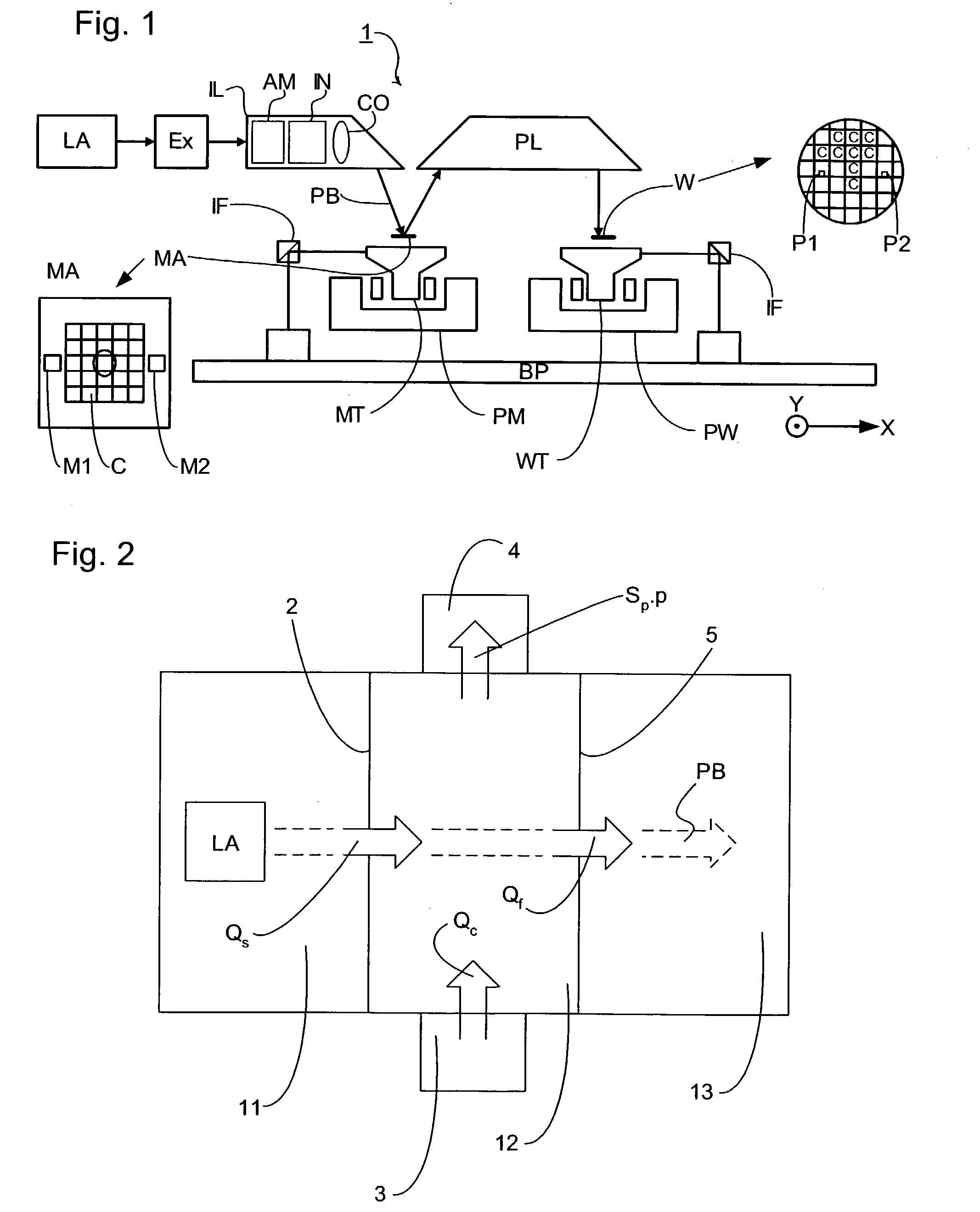
[0050] The following example calculates the fraction of source gas which enters the vacuum system of a lithography apparatus using the buffer system of the present invention.

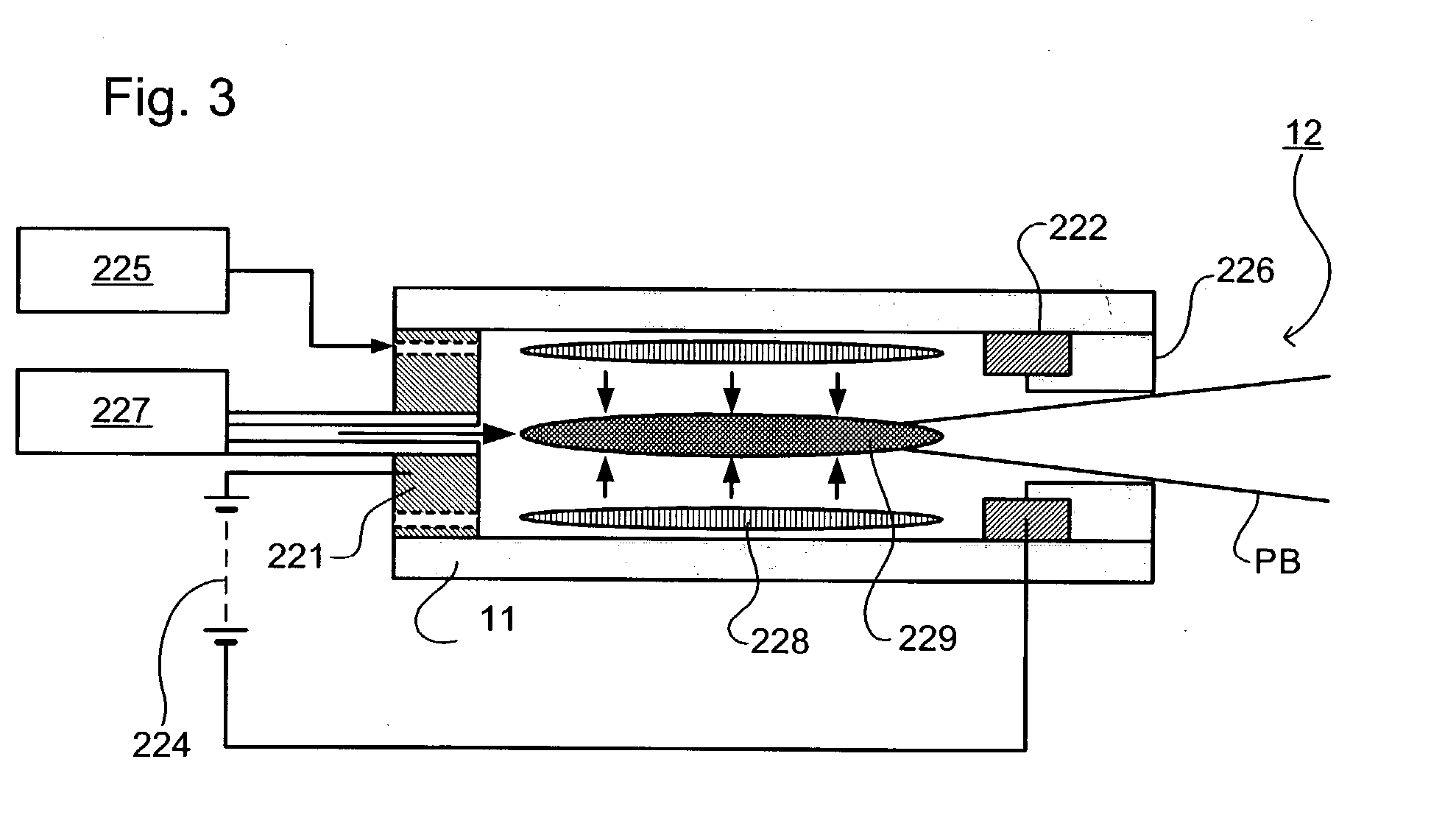
[0051] The apparatus used is that schematically depicted in FIG. 2. The zone 11 is a discharge plasma source, for example that depicted in FIG. 3, containing xenon as the source gas. The source comprises a source orifice defined by a flange, for example a flange 226 as depicted in FIG. 3 or a conical 20 mm thick flange. The buffer zone 12 contains argon at a pressure of 0.1 mbar and a temperature of 400K. The pressure in the source zone 11 is slightly higher than this. The zone 13 is evacuated. The mean free path of xenon atoms in argon is in the order of 1 mm for an argon temperature of 400K. This length, and the size of the source orifice, is small enough to ensure that the mixing of xenon and argon at the source orifice is diffusional.

[0052] The gas flow due to diffusional flux can be written as 2 Q s = kT4 d...


PUM


Abstract

A lithographic apparatus includes a first space containing a plasma source and also containing a source gas which may have a high absorption of radiation at the wavelength of the projection beam of the apparatus, this gas being restricted from entering the remainder of the lithographic system by a second space containing a buffer gas having a low absorption at the wavelength of the projection beam of the apparatus. The pressure of the buffer gas is lower than or equal to that of the source gas.

Description

[0001] 1. Field of the Invention[0002] The present invention relates to a lithographic projection apparatus and device manufacturing method.[0003] 2. Description of the Related Art[0004] The term "patterning device" as here employed should be broadly interpreted as referring to device that can be used to endow an incoming radiation beam with a patterned cross-section, corresponding to a pattern that is to be created in a target portion of the substrate. The term "light valve" can also be used in this context. Generally, the pattern will correspond to a particular functional layer in a device being created in the target portion, such as an integrated circuit or other device (see below). An example of such a patterning device is a mask. The concept of a mask is well known in lithography, and it includes mask types such as binary, alternating phase-shift, and attenuated phase-shift, as well as various hybrid mask types. Placement of such a mask in the radiation beam causes selective tr...

Claims


Application Information

Patent Timeline
IPC IPC(8): G03F7/20H01L21/027
CPCB82Y10/00G03F7/70908G03F7/70033G03F7/20
Inventor BAKKER, LEONJONKERS, JEROENVISSER, HUGO MATTHIEU
Owner ASML NETHERLANDS BV
Why Eureka
Try Eureka