Stent matrix

a technology of stents and matrixes, applied in the field of stent matrixes, can solve the problems of serious liver damage, restenosis of the vessel, and fatal complications

Inactive Publication Date: 2003-07-31
ANGIOMED GMBH & CO MEDIZINTECHNIK KG
View PDF12 Cites 161 Cited by
  • Summary
  • Abstract
  • Description
  • Claims
  • Application Information

AI Technical Summary

Problems solved by technology

However, stents are generally mesh-like so that endothelial and other tissues can grow through the openings resulting in restenosis of the vessel.
This is particularly because PTFE is extremely biocompatible causing little or no immunogenic reaction when placed within the human body.
Such blockage prevents or retards flow of bile into the intestine and can result in serious liver damage.
Because the liver is responsible for removing toxins from the blood stream, is the primary site for the breakdown of circulating blood cells and is also the source of vital blood clotting factors, blockage of the bile duct can lead to fatal complications.
However, such methods are far from ideal and suturing, in particular, is very labour intensive.
However, such a monolithically encapsulated stent may tend to be rather inflexible.
The outward flaring tends to enhance the anchoring power of the stent ends in the bodily tissue of the lumen in which the stent has been installed, but the provision of the imported beads on the free vertices of each flared end will tend to ameliorate the degree of trauma to which the flared ends might otherwise subject the tissue into which they protrude.
Although ePTFE has numerous favourable properties, it is relatively difficult to attach it to a stent.
Mechanical fasteners such as sutures have the disadvantage of interrupting the integrity of the ePTFE sheet so that leaking can occur.
The drawback with this approach is that the structural members of the stent are tightly surrounded and held by ePTFE.
Clearly, the greater percentage of length of the device that is fully encapsulated, the more the flexibility of the overall structure will be impeded.
Where two layers of ePTFE surround the stent, it may be significantly more difficult for cellular infiltration across the wall to occur.
There is some evidence that contact of the blood with a metal stent may result in local, limited thrombosis.
While this may be detrimental, there is also some evidence that some limited thrombosis results in enhanced healing.
The preferred bare stent designs (chosen for flexibility and low profile) do not permit transmission of a pulling force in a longitudinal axial direction.
The limited number of longitudinal connections has inadequate tensile strength to transmit the pulling force without failure.
In the case of sutured single layer device pulling on the covering may cause the suture holes to enlarge and even tear.
On the other hand, the very open structure of the expanded stent (FIG. 9) offers little resistance to tissue infiltration.

Method used


Image

  • Stent matrix
  • Stent matrix
  • Stent matrix

Examples


Embodiment Construction

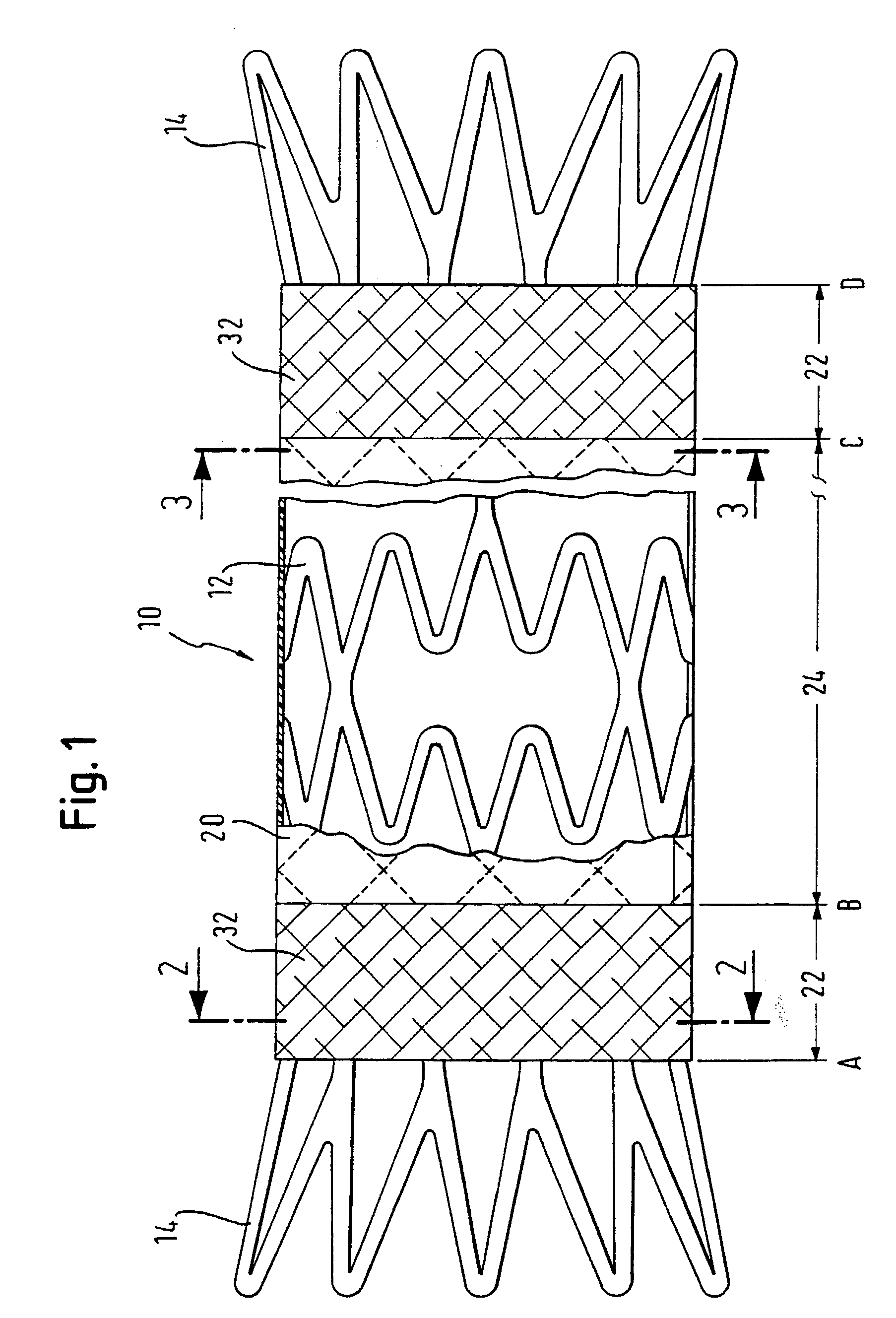
[0076] An esophageal stent graft was constructed from a Nitinol cylinder 0.3 mm thick. A laser controlled by a computer was used to cut a multiplicity of staggered cuts in the cylinder wall, parallel to the cylinder length, to create struts having a width of 0.167 mm. Cuts perpendicular to the length were also made in a mid-length portion of the tube length, for selective removal of scrap struts to enhance the flexibility of the mid-length section.

[0077] On a mandrel the tube is brought to its pre-set expanded configuration. The end portions of the expanded stent matrix cylinder were further expanded by the introduction of a tapered annulus between the stent matrix and the cylinder, one at each end of the stent. The stent matrix, on its mandrel, was then heated in an oven to "set" the configuration to be "remembered" by the shape memory alloy. Then, the scrap struts 32' were removed.

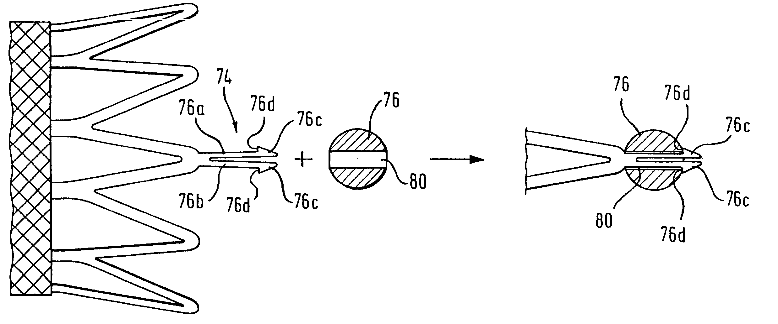
[0078] Following such heat-setting, the matrix was removed from the mandrel and a Nitinol bead, with ...


PUM

PropertyMeasurementUnit
widthaaaaaaaaaa
widthaaaaaaaaaa
diameteraaaaaaaaaa

Abstract

An object of this invention is to provide a radially expandable stent (1) that holds a passageway enlarged by placing the stent (1) into a lumen. The stent (1) comprises a cylindrical frame formed by a plurality of unit structures (11, 12, . . . 16, . . . ); said unit structures (11, 12, . . . 16, . . . ) formed into a closed zig-zag configuration including an endless series of straight sections (111) and joined by bends (112), and arranged face to face into a shape of multistage; connecting members (31, 33, 35, 37 . . . ), which connect said unit structures (11, 12, . . . 16, . . . ); and a mesh (91), which is wrapped around an outside of said frame.

Description

[0001] This invention relates to an elongate stent matrix which defines a surface in a closed loop surrounding an elongate flow path, and which is capable of expansion during deployment in a bodily lumen, from a small diameter delivery configuration to a large diameter lumen wall-supporting configuration;[0002] the matrix exhibiting a multiplicity of cells formed from struts, each of which cells has, at least in the delivery configuration, a length dimension along said flow path, a width dimension within said closed loop perpendicular to said flow path, and a thickness perpendicular to the length and width of the cell, with a first band of said cells at or near a first end of said matrix, and a further band of said cells at or near a second end of said matrix, opposite the first end;[0003] the matrix further exhibiting a first ring which includes at least one free vertex.[0004] Thus, this invention relates to prostheses to maintain patency of bodily lumens, and to precursors for suc...

Claims


Application Information

Patent Timeline
Patent Type & Authority Applications(United States)
IPC IPC(8): A61F2/00A61F2/07A61F2/91A61F2/915A61L31/00
CPCA61F2/07A61F2/91A61F2/915A61F2002/072A61F2002/075A61F2002/91508A61F2220/0075A61F2002/91558A61F2002/91591A61F2250/0098A61F2230/005A61F2230/0054A61F2220/005A61F2002/91525
Inventor LOMBARDI, SYLVIE
Owner ANGIOMED GMBH & CO MEDIZINTECHNIK KG
Why Eureka
Try Eureka