Eureka AIR delivers breakthrough ideas for toughest innovation challenges, trusted by R&D personnel around the world.

Multiplexer-demultiplexer module having an arrayed waveguide grating

Inactive Publication Date: 2003-08-07
ALCATEL OPTRONICS
View PDF7 Cites 10 Cited by
  • Summary
  • Abstract
  • Description
  • Claims
  • Application Information

AI Technical Summary

Benefits of technology

[0011] The object of the invention is to provide an optical module including an AWG component and a thin film filter that is capable, depending on the application, of processing wavelengths (or channels) individually or in given spectrum bands, with the module also providing high performance, being reliable, compact, and integrated.

Problems solved by technology

Such an AWG is not capable on its own of performing wavelength filtering.
The thin film filter components are interposed in the outlet waveguides from the AWG, thereby giving rise to additional optical loss.
Inserting components in that way gives rise to manufacturing problems and to reliability problems.

Method used


Image

  • Multiplexer-demultiplexer module having an arrayed waveguide grating
  • Multiplexer-demultiplexer module having an arrayed waveguide grating
  • Multiplexer-demultiplexer module having an arrayed waveguide grating

Examples


Embodiment Construction

[0035] The invention proposes making an integrated optical module including both an AWG multiplexer-demultiplexer component and a thin film filter, serving to pass a signal to its outlet only for certain wavelengths of inlet signal.

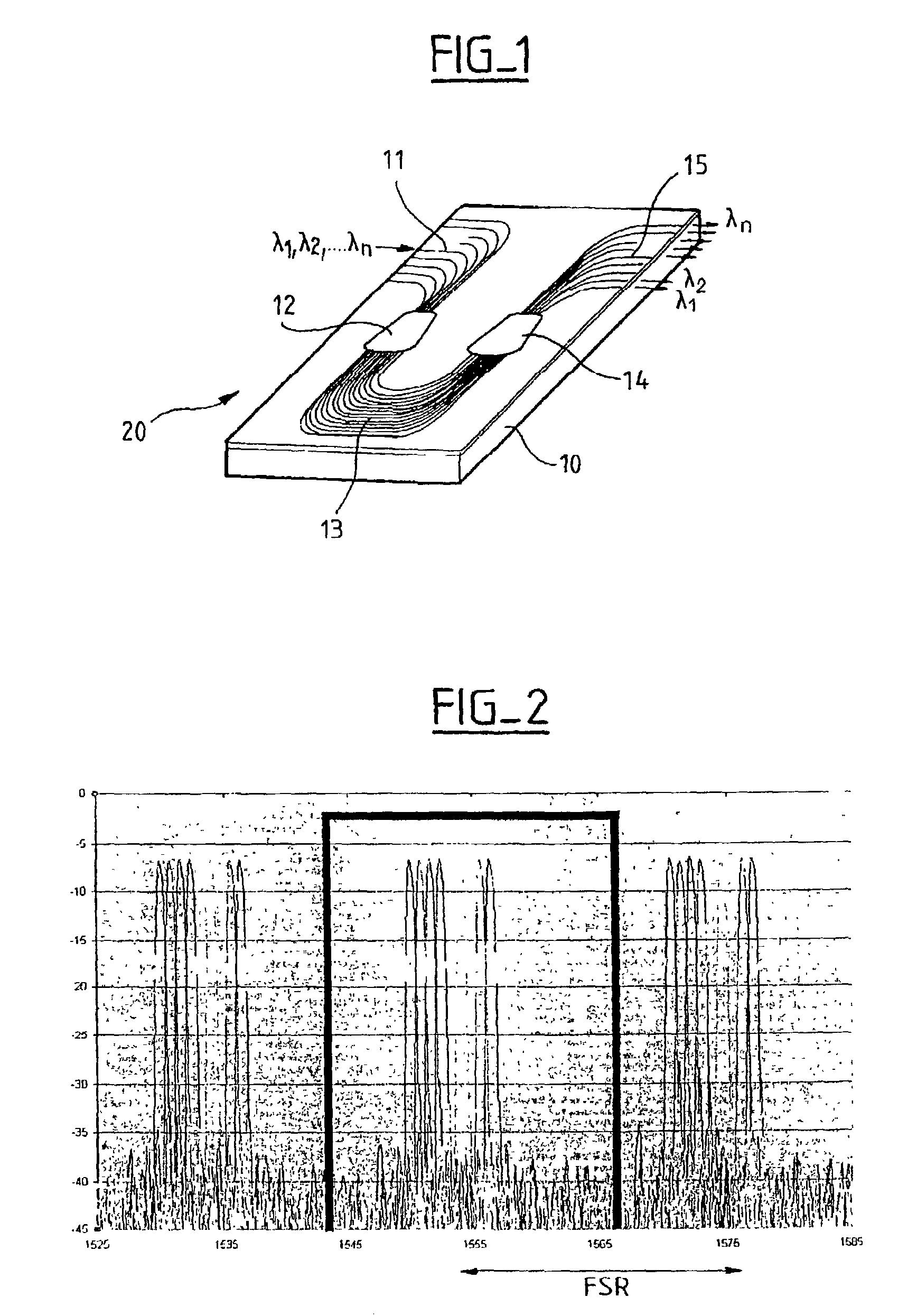
[0036] Such an optical module comprises at least one inlet optical fiber (a plurality if it is a multiplexer) and at least one outlet optical fiber (a plurality if it is a demultiplexer), these optical fibers being coupled to an AWG multiplexer-demultiplexer component.

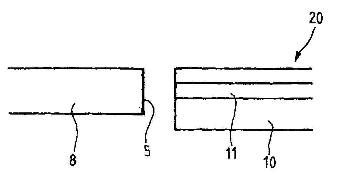
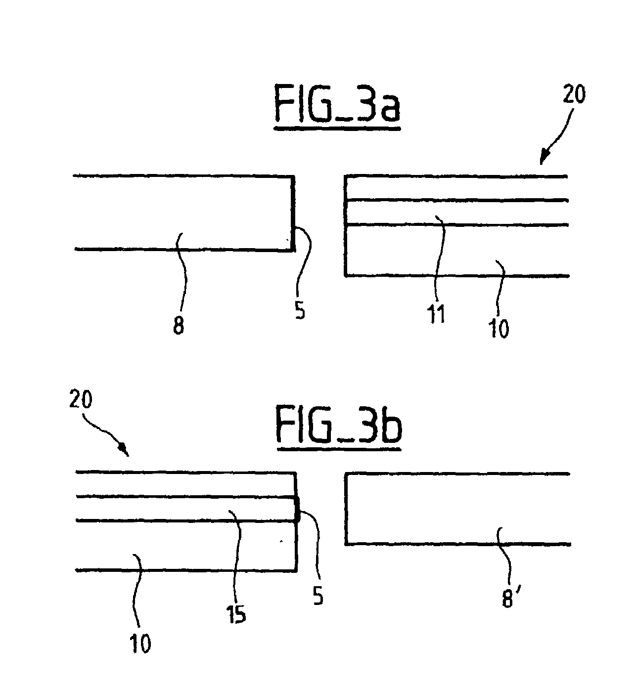
[0037] FIGS. 3a and 3b are diagrams showing the inlet and outlet optical coupling interfaces in a preferred embodiment of the invention.

[0038] As described above, the AWG 20 has at least one inlet waveguide 11 presenting an optical coupling interface with an inlet optical fiber 8, and at least one outlet waveguide 15 presenting an optical coupling interface with an outlet optical fiber 8'.

[0039] Such optical coupling interfaces are generally secured by adhesive. The optical fibers 8, 8' are ...


PUM


Abstract

In an optical module comprising an arrayed waveguide grating multiplexer-demultiplexer component having at least one inlet waveguide and at least one outlet waveguide, the module is integrated and comprises at least one inlet optical fiber and at least one outlet optical fiber, said inlet waveguide presenting an optical coupling interface with the inlet optical fiber and said outlet waveguide presenting an optical coupling interface with the outlet optical fiber, and a thin film filter is inserted directly at the optical coupling interface between the inlet and / or outlet waveguide(s) of the multiplexer-demultiplexer component and the inlet / outlet optical fiber(s) of the module.

Description

[0001] The present invention relates to the field of wavelength multiplexer-demultiplexer components, and more particularly to arrayed waveguide grating (AWG) multiplexer-demultiplexers. Such components are conventionally used in multiplexing and / or demultiplexing applications or for wavelength selection applications known as add and drop multiplexing.[0002] FIG. 1 is a diagram of a conventional AWG component 20 integrated on a substrate 10, e.g. a silicon substrate. Inlet waveguides 11 convey light signals at given wavelengths .lambda..sub.1, .lambda..sub.2, . . . .lambda..sub.n into an inlet coupler 12 leading to an array of waveguides 13. The light signals are subjected to phase shifts in the array of waveguides 13 and are subsequently focused by an outlet coupler 14 into outlet waveguides 15. Each optical signal is subjected to the following operations:[0003] diffraction in the inlet coupler 12 which is represented mathematically by the Fourier transform of the signal being diff...

Claims


Application Information

Patent Timeline
IPC IPC(8): G02B6/30G02B6/34
CPCG02B6/12016G02B6/12019G02B6/30G02B6/2938G02B6/29368
Inventor PATOZ, VINCENT
Owner ALCATEL OPTRONICS
Why Eureka
Eureka Blog
Learn More