
Pressure sensor module

Inactive Publication Date: 2003-08-14
ROBERT BOSCH GMBH
View PDF5 Cites 20 Cited by
  • Summary
  • Abstract
  • Description
  • Claims
  • Application Information

AI Technical Summary

Benefits of technology

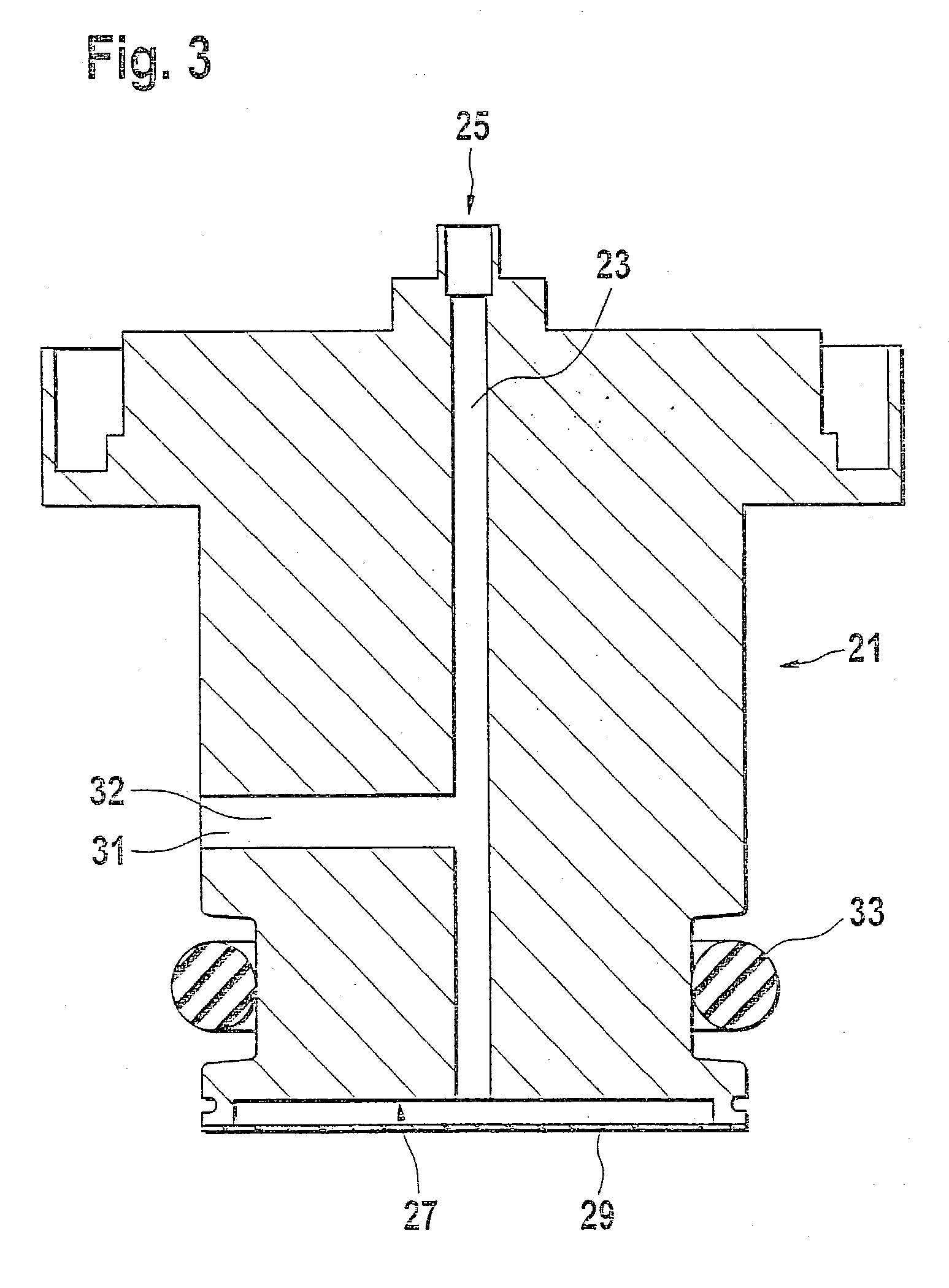
[0012] The pressure sensor module according to the invention, with the characterizing features of claim 1, has the advantage over the prior art that a pressure sensor module can be simply produced inexpensively and with a high degree of measurement precision for use in a corrosive environment. The high precision is achieved by sharply reducing the oil volume. As a result, in the pressure sensor module according to the invention, the influence of the thermal expansion of the oil volume on the measurement signal is very low. As a result, a rapid calibration of the pressure sensor chip, which is built into the sensor cell, can be executed in order to avoid the complex and long temperature steps in the finished pressure sensor module. A balancing of the sensor cells reduces the rejection costs in the calibration of the pressure sensor module. Since the sensor cell is smaller than the pressure sensor module, several sensor cells can be calibrated at the same time.[0013] Advantageous modifications and improvements of the pressure sensor module disclosed to claim 1 are possible by means of the steps taken in the dependent claims.[0014] Claim 2 discloses an advantageous adapter of the pressure sensor module. The adapter has a hole through it, which is connected at one end to a pressure fitting of the sensor cell and at the other end, is closed by means of a separating membrane; the volume thus enclosed is advantageously filled with a fluid. The adapter has a simple design and is therefore inexpensive.[0015] It is advantageous if the adapter has an additional opening through which the fluid can be introduced into the hole.[0016] A printed circuit board, for example with components on it, can advantageously be connected to external electrical connections of the pressure sensor chip of the sensor cell. This allows additional components for improving the electromagnetic compatibility to advantageously be mounted onto the printed circuit board.[0017] The pressure sensor module housing can advantageously contain the electrical plug connections.

Problems solved by technology

A sensor cell of this kind cannot be used with intensely corrosive mediums since the corrosive medium corrodes the sensor chip or the gel.
However, this gel is also corroded by the corrosive medium and since as a gel, it does not have great chemical resistance or mechanical strength, it changes in shape over time, which has an influence on the measuring results.
In addition, in the known pressure sensor module, a defect of the pressure sensor chip can only be detected once it is completely assembled.
As a result, the costs arising from rejections are higher since the finished component has to be discarded.
With this type of seal, there is the danger, for example in the event of a damaged O-ring or when particles adhere to the sealing surface, of oil escaping from the interior of the sensor.
In this connection, there is the danger of the pressure sensor chip, which is designed for low pressure measurement ranges, being damaged by the high pressure for displacing the residual air in the housing.
The integration of these capacitors into the housing in the known sensor module is complicated and increases the manufacturing costs for the pressure sensor module.
The design is very complex and includes a large dead volume of the transmitting medium.
This protective layer changes the reaction behavior and measurement behavior of the membrane in a negative fashion and also does not offer sufficient protection over a long time since this protective layer must be thin enough to allow the sensor membrane to continue to flex in a favorable fashion.
In this design, an O-ring must once again be used to produce a seal, which brings about the O-ring-related problems described above.

Method used


Image

  • Pressure sensor module
  • Pressure sensor module
  • Pressure sensor module

Examples


Embodiment Construction

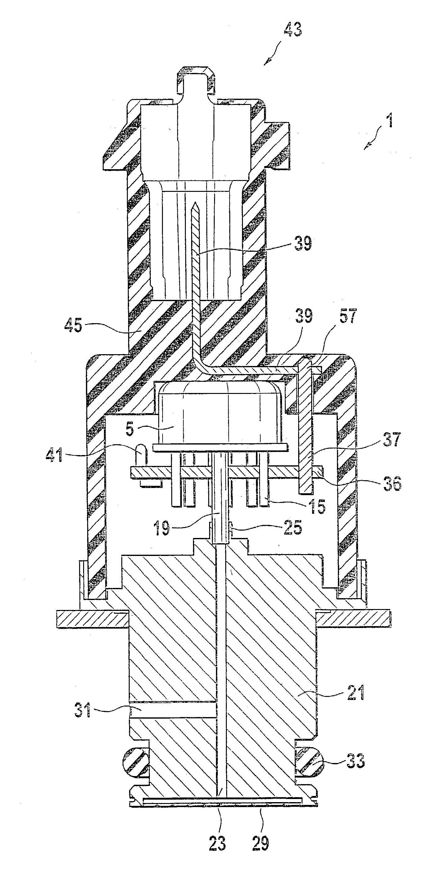
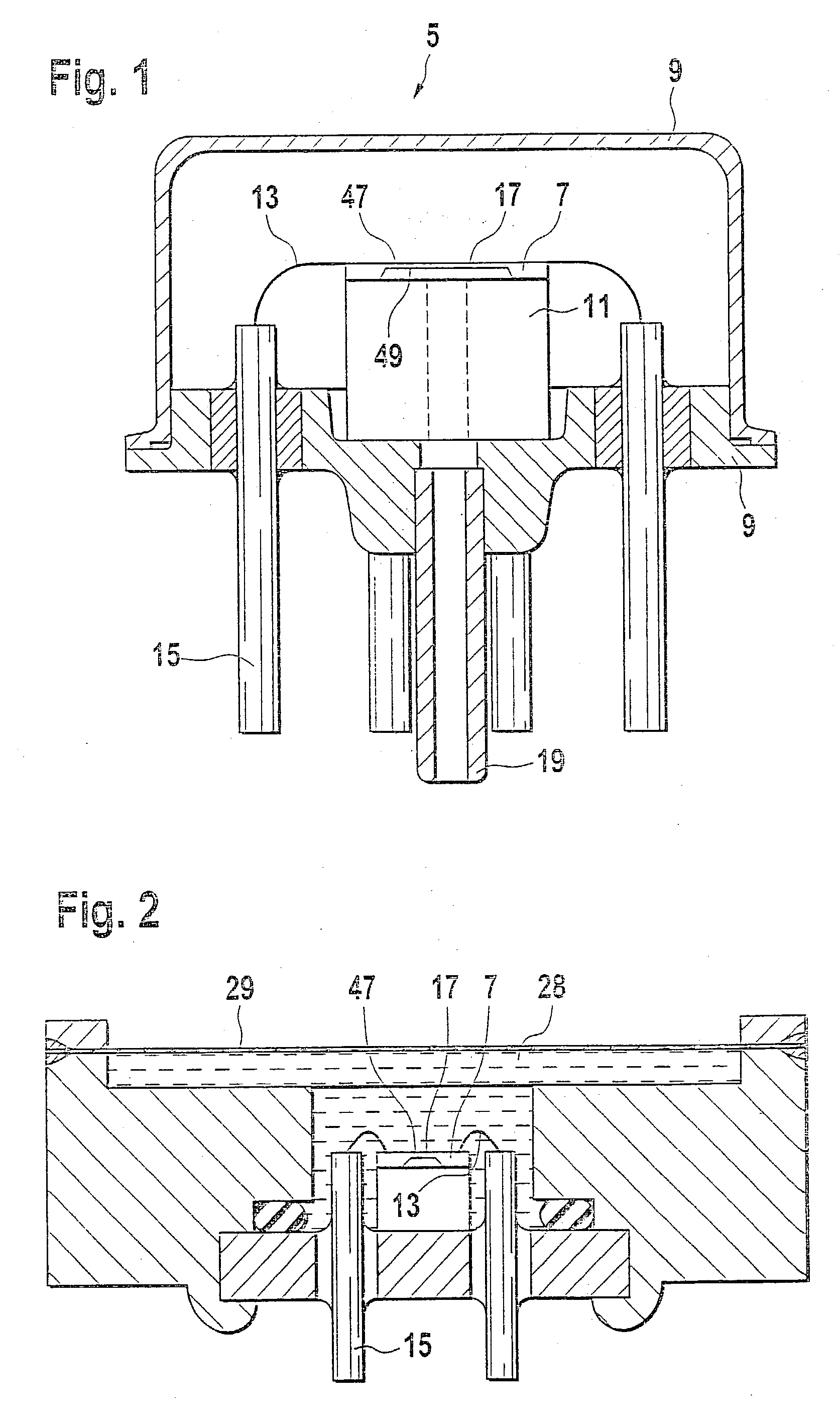
[0028] FIG. 1 shows an axial cross section through a sensor cell 5, which contains a pressure sensor chip 7 and is used for example in the pressure sensor module 1 according to the invention (FIG. 5). The pressure sensor chip 7 is mounted on a glass support 11, for example by means of anodic bonds. The sensor cell 5 has a for example two-piece sensor housing 9 in which the glass support 11 is affixed by means of a soldering process. Inside the sensor housing 9, bonding wires 13 electrically connect the pressure sensor chip 7 to electrical sensor connection elements 15, which protrude through the sensor housing 9. For example, the pressure sensor chip 7 has a membrane 17, whose underside 49 is acted on by a medium, which is conveyed by means of a pressure fitting 19, for example an additional metal tube, which is shown with dashed lines. The membrane 17 can flex as a result of a pressure acting on it so that the deflection results in a measurement signal that is transmitted by means ...


PUM


Abstract

In a pressure sensor module according to the prior art, which is intended for detecting the pressure of a corrosive medium, the conventional sensor cell with a pressure sensor chip is modified in order to protect it from corrosion, which results in a large volume for a pressure-transmitting fluid. This is disadvantageous for the calibration and for a high degree of measurement precision. In a pressure sensor module (1) according to the invention, a conventional sensor cell (5) is used that has an adapter (21) connected to it, which has a very small volume for a pressure-transmitting medium.

Description

PRIOR ART[0001] A pressure sensor module contains, for example, piezoresistive sensor cells, which are used for a broad range of applications, for example a pressure measurement in an intake manifold of a motor vehicle. In this connection, a pressure sensor chip is soldered to a socket, which has glass feedthroughs for external electrical connections. Then electrical connections of the pressure sensor chip are electrically contacted with the external electrical connections by means of bonding wires.[0002] The pressure of a medium acts, for example, on a back side of the pressure sensor chip by means of a metal tube, which is soldered to the socket. For absolute pressure measurements, a metal cap is welded to the socket under vacuum. For relative pressure measurements, the cap has an opening. The pressure sensor chip is protected, for example by means of a gel, against external influences. A sensor cell of this kind cannot be used with intensely corrosive mediums since the corrosive ...

Claims


Application Information

Patent Timeline
IPC IPC(8): G01L9/00G01L19/06
CPCG01L19/003G01L19/0084G01L19/0645G01L19/0672H01L2224/48091G01L19/147G01L19/143H01L2924/00014G01L19/06
Inventor SCHEURICH, HEIKOMAST, MARTINROGGE, BERTHOLDHABIBI, MASOUD
Owner ROBERT BOSCH GMBH
Learn More